43
HCD-SB100/SB200
SECTION 6
ELECTRICAL ADJUSTMENT
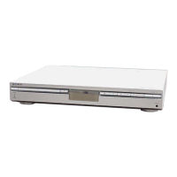
+
–
DVD board
oscilloscope
PDM01 pin
2
(RFOUT)
PDM01 pin
6
(GND PD)
Procedure:
1. Connect an oscilloscope to PDM01 pin 2 (RFOUT) and
PDM01 pin 6 (GND PD) on the DVD board.
2. Turn the power on.
3. Set the test disc (DVD: TDV-520CSO, CD: LUV-P01) on the
tray and touch the B button to playback.
4. Confirm that oscilloscope waveform is clear and check RFOUT
signal level is correct or not.
Note: A clear RFOUT signal waveform means that the shape “◊” can be
clearly distinguished at the center of the waveform.
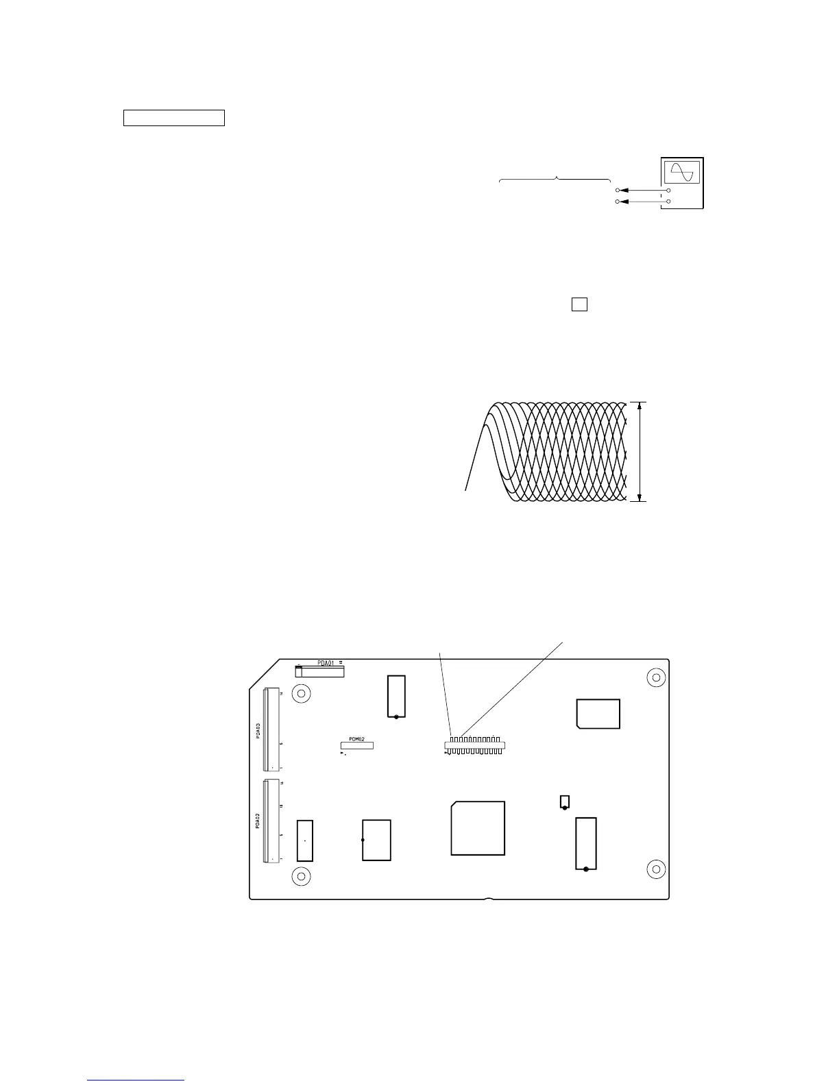
Checking Location: DVD board (COMPONENT SIDE)
IC5C1
IC5A1
IC501
IC506
IC505
IC201
IC202
1
11
10
2
[DVD BOARD](COMPONENT SIDE)
PDM01 pin
2
(RFOUT)
PDM01 pin
6
(GND PD)
PDM01
1
2
22
23
[RFMON Level Check]
Connection:
Ver. 1.2
DVD SECTION
[TEST DISC LIST]
Use the following test disc on test mode.
TDV-520CSO (DVD-SL): PART No. J-2501-236-A
LUV-P01 (CD): PART No. 4-999-032-01
TDV-540C (DVD-DL): PART No. J-2501-235-A
Note: Do not use exiting test disc for DVD.
 Loading...