25
Menu Operations
Notes
• The button for which the TAKE function has been set
cannot be used as a source select button.
• The TAKE button set in Menu item N will be enabled in
AUX mode as well.
Setting the SHIFT function
What is the SHIFT function?
Normally you can use sources 1 through 32 and reentry
M/E1 through M/E3, and P/P1. When you use the SHIFT
function, you can use sources 33 through 64 and reentry
M/E4 through M/E6, and P/P2.
Setting procedure
1
Select the number of the button to which the SHIFT
function is to be set using the cursor keys,.
2
Press [F].
“SHIFT” appears, and the SHIFT function is assigned
to the button selected in step 1 (hereinafter called the
SHIFT button).
Notes
• The button for which the SHIFT function has been set
cannot be used as a source select button.
• The SHIFT button set in Menu item N will be enabled in
AUX mode as well.
Menu Item R: SET ROUTE
Purposes
Menu item R enables you to set the routing function.
What is the routing function?
If you cannot expand the number of inputs using cascade
connections, you may connect sources of a switcher to the
destinations of another switcher to achieve expansion. In
such condition, you may set a function to display the
source selected for the destination connected to an
extended input when you select an input to the extended
device, and support the required switching operation.
Such a function that enables input expansion with a device
without cascading capability is called a “routing function.”
By using the routing function, you can simply operate
sources used for multiple destinations as if switching
sources for a single destination.
Even when such input expansion is repeated 4 times at
maximum, the routing function enables you to search for
destinations tracing back via the expanded inputs and to
obtain a display of the appropriate source.
To display the actually selected source name, you must set
the routing function with the terminal.
Then when you select a crosspoint set for the routing
function, the source on switcher A is searched for, and the
name is displayed.
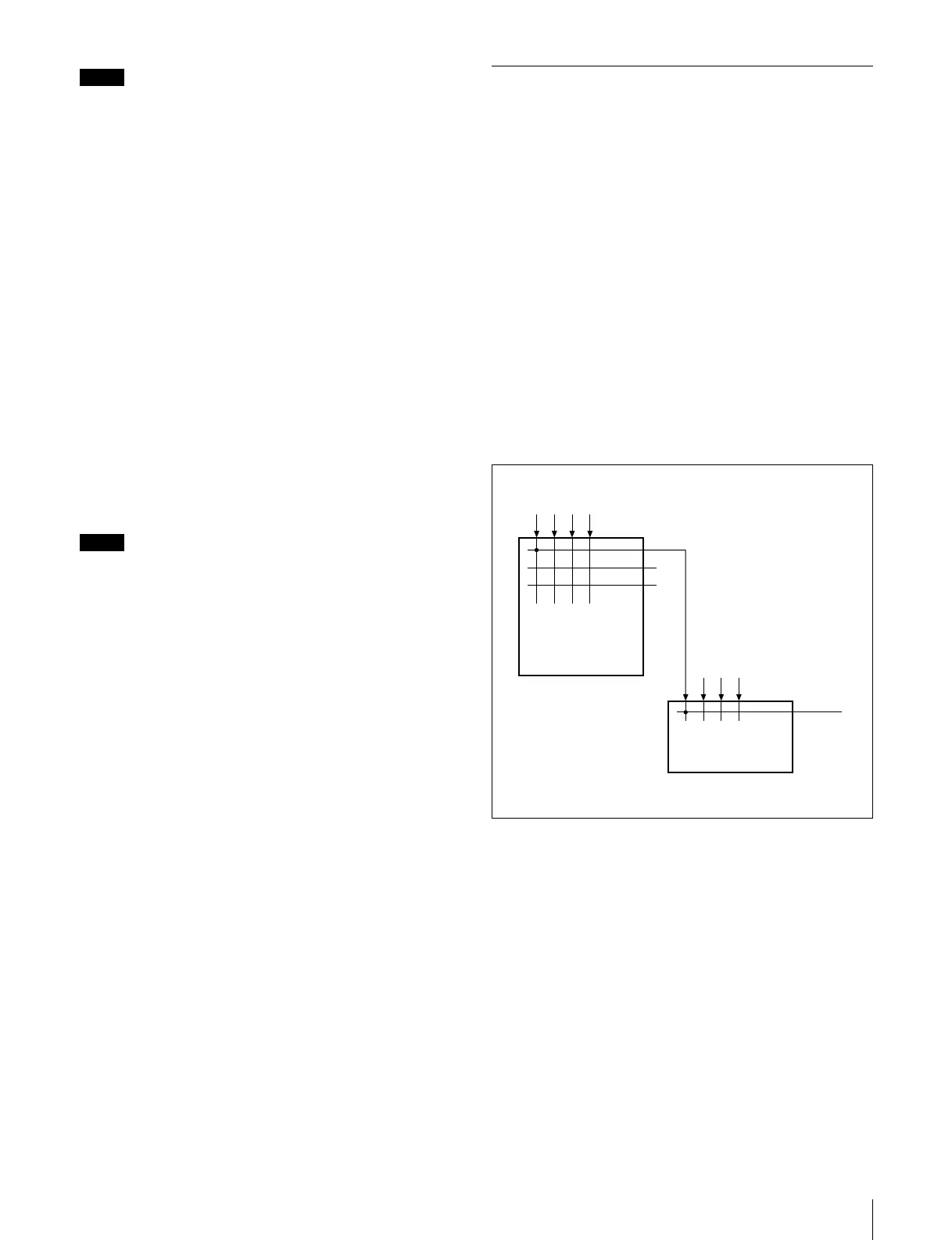
For example, when a crosspoint is switched on switcher A
in the figure, normally IN5 appears as the source name. If
the routing function has been set, the source name selected
on switcher A appears.
To activate the routing function, set the destination of
switcher A, the destination and source of switcher B, and
the level, in that order.
IN
5
OUT
1
OUT 2
IN
1234
678
Sources of switcher A
Destinations of
switcher A
HDS-X3600
(Level 1)
Switcher A
Expanded input
(source of
switcher B)
Destination of
switcher B
DVS-7000
(Level 1)
Switcher B
 Loading...