23
Menu Operations
Examples of a destination offset local
phantom
Use this type of phantom when there are multiple
destination select buttons, or when you want to always
select a specific source in the same pattern even if the
destination is changed from an X-Y control panel.
Example 1
A source (audio source AUD007 for example) of a level is
to be assigned to multiple sources of another level (video
source IN001 and IN004 for example).
Example 2
A pair of crosspoints (multiple audio channels, video key
signals for example) is to be set.
Menu Item N: SET PANEL TABLE (for
Router mode)
Purposes
Menu item N enables you to set which source or
destination is to be selected with which source/destination
select button in RTR mode.
For a button to be used for the phantom, enter the phantom
name on the source side.
You may also assign the monitor function, VTR control
function, or level select function on the source side.
Notes
• The functions other than select buttons can be used only
in Source mode.
• The monitor function is enabled in RTR mode only.
Calling the setting display of menu item N
Press [N] on the selection display to select menu item N.
The setting display of menu item N appears.
Setting display (example)
The subsequent operation depends on the function to be
set.
To return to the selection display of the Setup
Menu
Press [Ctrl]-[E] on each setting display.
To return to the primary station menu
Press [Ctrl]-[D].
Source name for each level
Setting of destination- offset local
phantom
Source
name
LEVEL 1 LEVEL 2
IN001 IN001 AUD007 IN001: DST+000<IN001-10000000
IN001: DST+000<AUD007-01000000
IN004 IN004 AUD007 IN004: DST+000<IN004-10000000
IN004: DST+000<AUD007-01000000
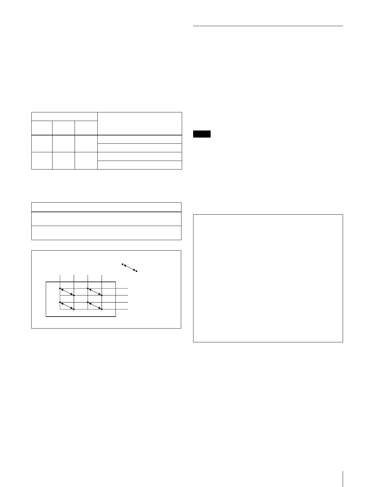
Setting of Destination Offset Phantom
IN001: DST+000<IN001-10000000
IN001: DST+001<IN002-10000000
IN003: DST+000<IN003-10000000
IN003: DST+001<IN004-10000000
OUT
1
OUT
2
OUT
3
OUT
4
IN
1IN
2IN
3IN
4
: Switching by pairs
SONY ROUTING SYSTEM SETUP MENU MKS-8082 V1.00 STATION NUMBER 6
SET PANEL TABLE (SOURCE) CONTROL DESTINATION = OUT017
01 KEY=IN001 02 KEY=IN002 03 KEY=IN003 04 KEY=IN004
05 KEY=IN005 06 KEY=IN006 07 KEY=IN007 08 KEY=IN008
09 KEY=IN009 10 KEY=IN010 11 KEY=IN011 12 KEY=IN012
13 KEY=IN013 14 KEY=IN014 15 KEY=IN015 16 KEY=IN016
17 KEY=IN017 18 KEY=IN018 19 KEY=IN019 20 KEY=IN020
21 KEY=IN021 22 KEY=IN022 23 KEY=IN023 24 KEY=IN024
25 KEY=IN025 26 KEY=IN026 27 KEY=IN027 28 KEY=IN028
29 KEY=IN029 30 KEY=IN030 31 KEY=IN031 32 KEY=IN032
SET RE-ENTRY BUTTON (multi effect key)
M/E1=IN121 M/E2=IN122 M/E3=IN123 P/P1=IN124
SET PANEL TABLE (DESTINATION)
01 KEY=OUT017 02 KEY=OUT018 03 KEY=OUT019 04 KEY=OUT020
05 KEY=OUT021 06 KEY=OUT022 07 KEY=OUT023 08 KEY=OUT024
09 KEY=OUT025 10 KEY=OUT026 11 KEY=OUT027 12 KEY=OUT028
13 KEY=OUT029 14 KEY=OUT030 15 KEY=OUT031 16 KEY=OUT032
0=IN 1=OUT 2=SONY 3=VTR 4=SUP 5=CB 6=AIR 7=ME
8=PGM 9=CL A=SL B=L C=RET D=MIX E=JEEP F=OSC
G=L/A H=REM I=CAM J=STDO K=AUX L=COV M=BS N=CS
O=SAT P=CG Q=WETH R=TEST S=HD T=D1- U=D2- V=SEG
F1
: MOVE F2
: PgDn Ctrl-E
: MENU Ctrl-N
: DESCRIP.NAME T
: TAKE M
: MONI F
: SHIFT
 Loading...