NSX-24GT1/32GT1/40GT1/46GT1 9
DISASSEMBLY/PART NUMBER INFORMATION
NOTE: The components identied by shading
and
!
mark are critical for safety. Replace only
with part number specied.
NOTE: The components identied by a red outline and a mark contain
condential information. Specic instructions must be adhered to whenever
these components are repaired and/or replaced.
See Appendix A: Encryption Key Components in the back of this manual.
REF. NO. PART NO. DESCRIPTION [ASSEMBLY INCLUDES] REF. NO. PART NO. DESCRIPTION [ASSEMBLY INCLUDES]
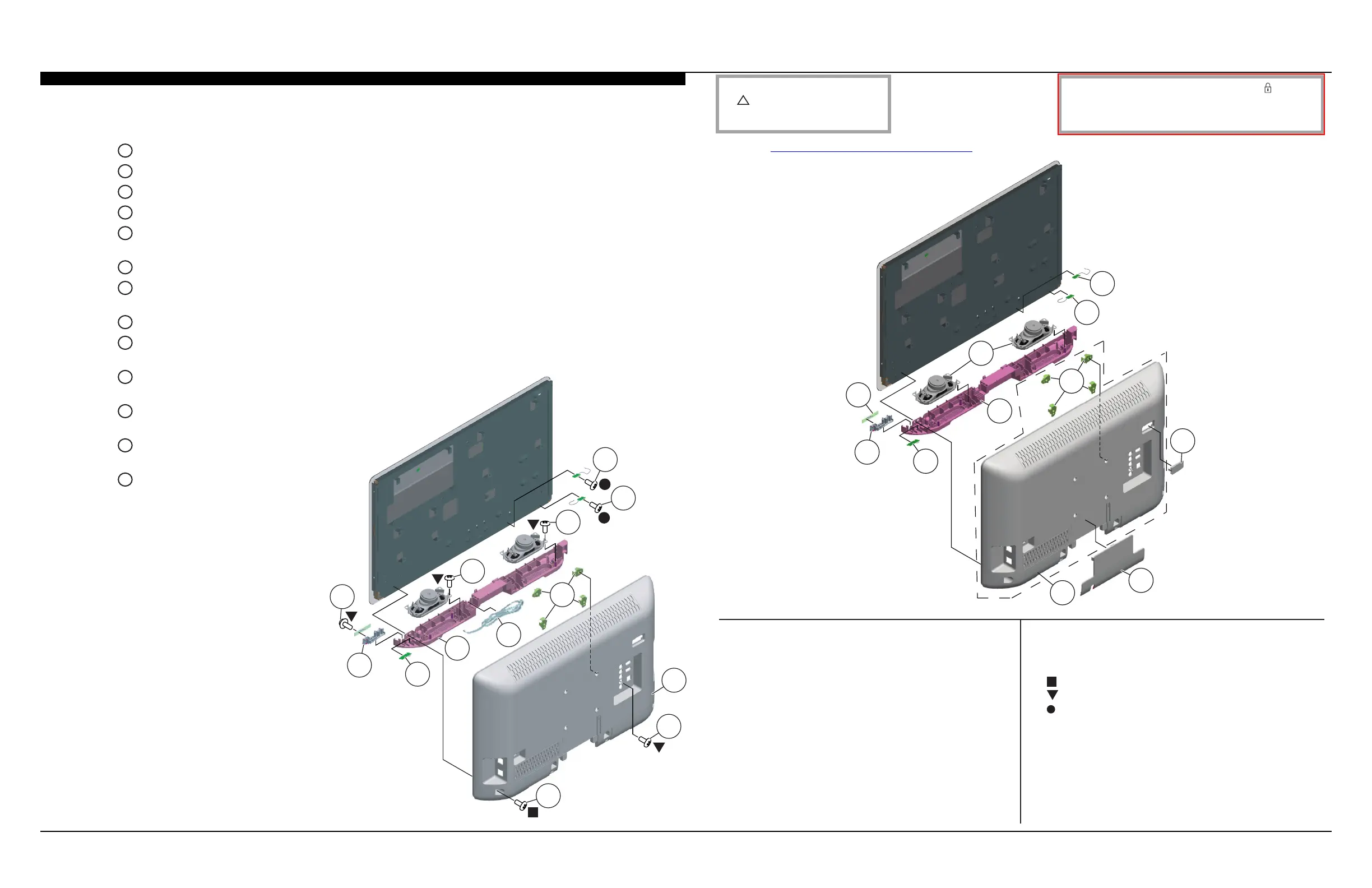
1-2. REAR COVER, SPEAKERS, ANTENNAS, RF MODULE AND HA BOARD REMOVAL
1-2-1. NSX-24GT1 ONLY
(Check the Sony Electronics Service Information website for any additional service related issues for this model.)
59 1-858-466-11 LOUDSPEAKER
60 1-754-735-21 ANTENNA
61 1-754-735-11 ANTENNA
7-682-962-01 SCREW, +PSW M4X10
7-685-648-71 SCREW, +BVTP 3X12 TYPE2 IT-3
2-580-592-01 SCREW, +PSW M3X8
A
Remove 4 screws from Rear Cover to detach from LCD Panel
B
Remove 1 screw from Rear Cover to detach from Terminal Area
C
Lift up Rear Cover from bottom side to detach from Glass Assembly
D
Slide out 4 Vesa Brackets to detach from Rear Cover
E
Disconnect 1 connector from G (Power) Board and detach AC Power
Supply Cord from Speaker Cover
F
Lift up Speaker Cover to detach from LCD Panel
G
Release 1 clip and disconnect 1 connector to detach RF Module from
Speaker Cover
H
Release 1 clip to detach Power Button from Speaker Cover
I
Remove 1 screw from HA Board and disconnect
1 connector, then lift up to remove from Power Button
J
Remove 4 screws and disconnect
2 connectors to detach Speaker Right from Speaker Cover
K
Remove 4 screws and disconnect 2 connectors to
detach Speaker Left from Speaker Cover
L
Remove 1 screw from Antenna to detach
from Main Frame
M
Remove 1 screw from Antenna to detach
from Main Frame
D
C
F
H
G
A
B
K
J
I
E
L
M
51 X-2548-950-1 REAR COVER (24) ASSEMBLY [54]
52 4-198-068-01 AC DOOR (24)
53 4-198-069-01 ECS COVER
54 4-198-018-01 BRACKET, VESA (SS)
55 4-198-046-01 SPEAKER COVER (24)
56 1-489-179-11 RF MODULE
57 4-198-047-01 POWER BUTTON
58 A-1787-299-A HA BOARD, MOUNTED
54
55
52
53
57
56
51
59
58
60
61
 Loading...