NSX-24GT1/32GT1/40GT1/46GT1 11
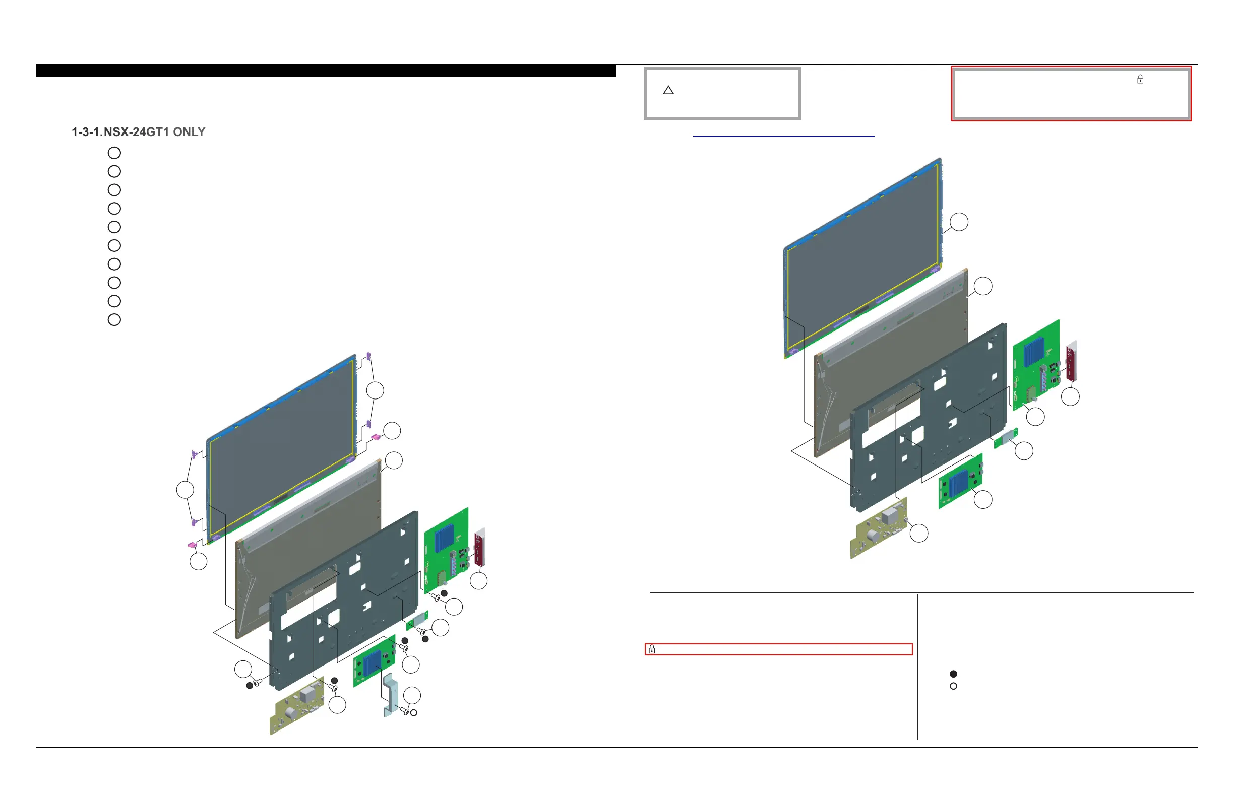
DISASSEMBLY/PART NUMBER INFORMATION
NOTE: The components identied by shading
and
!
mark are critical for safety. Replace only
with part number specied.
NOTE: The components identied by a red outline and a mark contain
condential information. Specic instructions must be adhered to whenever
these components are repaired and/or replaced.
See Appendix A: Encryption Key Components in the back of this manual.
REF. NO. PART NO. DESCRIPTION [ASSEMBLY INCLUDES] REF. NO. PART NO. DESCRIPTION [ASSEMBLY INCLUDES]
(Check the Sony Electronics Service Information website for any additional service related issues for this model.)
A
Release 1 clip to detach Side Jack Cover from BA Board
B
Remove 6 screws and disconnect 6 connectors from BA Board to detach from Main Frame
C
Remove 2 screws and disconnect 1 connector from WLAN Card to detach from Main Frame
D
Remove 4 screws and disconnect 4 connectors from M Board to detach from Main Frame
E
Remove 2 screws from AL Plate to detach from M Board
F
Remove 6 screws and disconnect 7 connectors from G Board to detach from Main Frame
G
Remove 4 screws from Main Frame to detach from Glass Assembly
H
Slide up, then out 4 Side Panel Supports to release LCD Panel from Glass Assembly
I
Slide out 2 Bottom Panel Supports to release LCD Panel from Glass Assembly
J
Carefully Lift up LCD Panel to remove from Glass Assembly
NOTE: The AL Plate is not included with the M Board and must be reattached to the
replacement M Board
1-3. G/GE6/GE7A/GE7B (POWER) BOARDS, BA BOARD, M BOARD, WIRELESS LAN CARD
AND LCD PANEL REMOVAL
155 X-2548-976-1 SIDE JACK COVER (24) ASSEMBLY
156 NA LCD PANEL
FOR ALL LCD PANEL PART NUMBER INFORMATION
REFER TO THE LCD PANELS SERVICE MANUAL
157 A-1785-484-A GLASS ASSEMBLY SERVICE (24)
2-580-592-01 SCREW, +PSW M3X8
7-682-950-01 SCREW, +PSW M3X12
J
I
I
H
H
D
G
E
A
B
C
F
156
157
152
155
154
153
151
151 1-857-840-11 G (POWER) BOARD
152 A-1787-298-A M BOARD, MOUNTED
153 1-487-819-11 CARD, WIRELESS LAN
154 A-1783-118-A BA BOARD, MOUNTED
 Loading...