HT-X9000F/XF9000
24
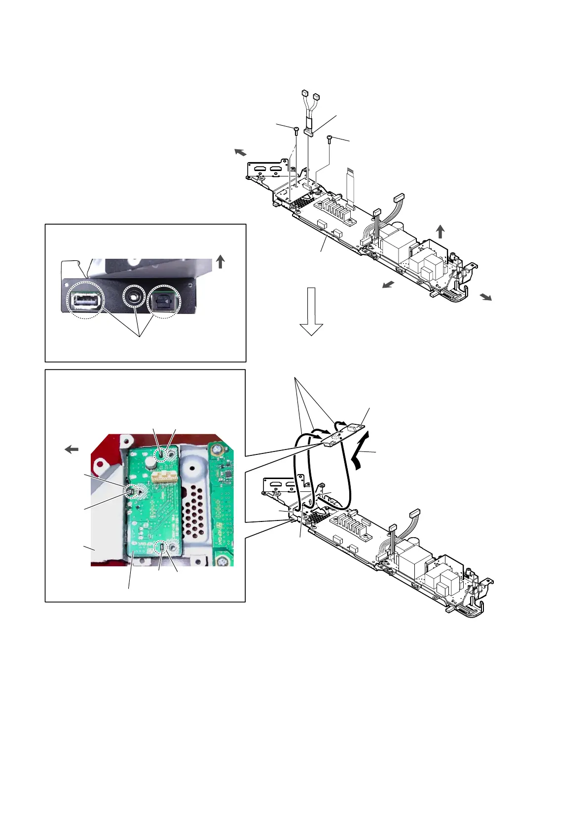
2-18. SK1-JACK BOARD
right side
left side
2 screw
(BVTP3 u 8)
1 SK1-JACK board cable
connector (CN1601)
front side
top side
top side
main chassis block
2 two screws
(BVTP3 u 8)
4 Draw the jack and two connectors
out of the three holes in chassis.
3 Remove the SK1-JACK board
in the direction of the arrow.
5 SK1-JACK board
(See Fig. F)
hole
hole
hole
hole
,QVWDOODWLRQSRVLWLRQRIWKH6.-$&.ERDUG
–7RSYLHZ–
–6LGHYLHZ–
left side
hole
rib
rib
rib
groove
SK1-JACK board
chassis
Check that the jack and two connectors are installed
on the holes of the chassis correctly.
1RWHDERXWLQVWDOOLQJWKH6.-$&.ERDUG
)LJ)!
Note:
When installing the SK1-JACK board,
align the two holes and groove with
the three ribs.
 Loading...