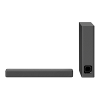
HT-X9000F/XF9000
4
SECTION 1
SERVICING NOTES
UNLEADED SOLDER
Boards requiring use of unleaded solder are printed with the lead-
free mark (LF) indicating the solder contains no lead.
(Caution: Some printed circuit boards may not come printed with
the lead free mark due to their particular size)
: LEAD FREE MARK
Unleaded solder has the following characteristics.
• Unleaded solder melts at a temperature about 40 °C higher
than ordinary solder.
Ordinary soldering irons can be used but the iron tip has to be
applied to the solder joint for a slightly longer time.
Soldering irons using a temperature regulator should be set to
about 350 °C.
Caution: The printed pattern (copper foil) may peel away if
the heated tip is applied for too long, so be careful!
• Strong viscosity
Unleaded solder is more viscous (sticky, less prone to fl ow)
than ordinary solder so use caution not to let solder bridges
occur such as on IC pins, etc.
• Usable with ordinary solder
It is best to use only unleaded solder but unleaded solder may
also be added to ordinary solder.
NOTE OF REPLACING THE FUSE
The fuse is or could be in the neutral. When a fuse is being re-
placed, the main plug shall be disconnected from the AC outlet to
prevent electric shock.
ADVANCE PREPARATION WHEN CONFIRMING OP-
ERATION
All of the units included in the HT-X9000F (SA-X9000F/SA-
WX9000F/Remote control) or HT-XF9000 (SA-XF9000/SA-
WXF9000/Remote control) are required to confi rming operation
of SA-WX9000F/WXF9000. Check in advance that you have all
of the units.
DISCHARGE PROCESSING
Before checking the operation of the boards for the electric shock
prevention, perform the discharge processing by connecting the
resistor at both ends of the specifi ed capacitor with referring to the
fi gure below.
Note: Be sure to discharge using a resistor of 800 or higher.
– POWER Board (Conductor Side) –
C923
C917
800 :/2 W
800 :/2 W
NOTE OF PERFORMING THE OPERATION CHECK IN
THE STATE THAT HEAT SINK IS REMOVED
When performing the operation check in the state that this unit is
disassembled, it is possible to perform the operation check in the
state that heat sink is removed. However, don’t perform the opera-
tion check in the long time, and perform the operation check in the
volume state as low as possible.
The SERVICING NOTES contains important information for servicing. Be sure to read this section before repairing the unit.
ABOUT THE PROTECTION
All the indicators flash quickly and
the system is turned off.
q Disconnect the AC power cord (mains
lead) and make sure nothing is
obstructing the ventilation holes of
the system.
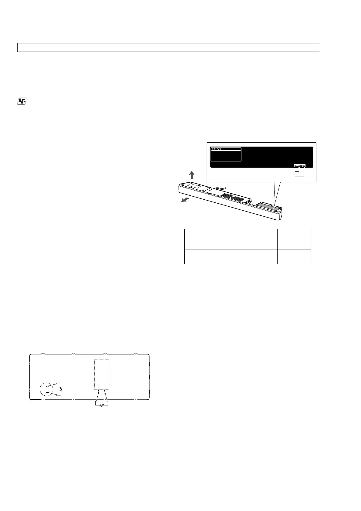
MODEL IDENTIFICATION
Distinguish by Part No. and Destination code of the model number
label on the bottom side of the main unit.
front side
bottom side
MODEL NUMBER LABEL
Destination code
Part No.
Destination Part No.
Destination
code
X9000F: US, CND
4-724-090-0[]
UC2
XF9000: AEP
4-724-092-0[]
CEL
XF9000: UK
4-724-093-0[]
CEK
DESTINATION ABBREVIATIONS
The following abbreviations for model destinations are used in this
service manual.
• Abbreviations
AEP : European area (Except for UK, Ireland), East European
area, CIS area (Moldova) and Middle East area (Israel,
Jordan) models
CND : Canadian and Latin American area (Puerto Rico) models
UK : European area (UK and Ireland) model
 Loading...