HT-X9000F/XF9000
26
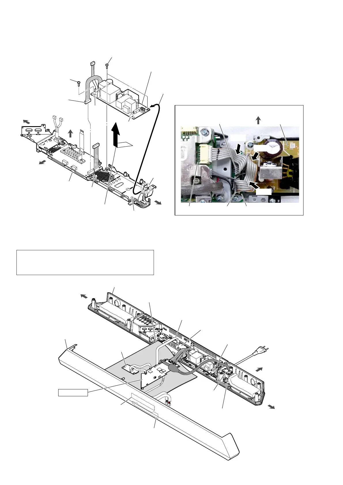
2-20. POWER BOARD
hole
hole
rib
rib
right side
left side
Press.
Press.
Press.
:LUHVHWWLQJUHIHUHQFH
CN6002
SK1 AMP board
–7RSYLHZ–
rear side
POWER board
CN6001
MAIN board
front side
top side
main chassis block
5 POWER board
Note:
When installing the POWER board,
align the two ribs and two holes.
1 POWER board cable
connector (CN6002)
2 two screws
(BVTP3 u 8)
2 screw
(BVTP3 u 8)
3 Remove the POWER board
in the direction of the arrow.
slit
4 Draw the corner of POWER
board out of the slit.
2-21. MAIN BOARD SERVICE POSITION
insulating sheet
SK1-JACK board
rear side
POWER board
SK1-TOUCH board
SK1 LED board
SK1 AMP board
SK1-WS-CHUKEI board
bluetooth module
left side
right side
MAIN board
bottom cabinet block
top cabinet block
flexible flat cable (28P)
(L = 330 mm)
(See Note)
Note: The service position below cannot be performed with the fl ex-
ible fl at cable (L = 60 mm) used with the unit.
Refer to “FLEXIBLE FLAT CABLE FOR THE EXTENSION”
on page 7, and use a long fl exible fl at cable (L = 330 mm).