EasyManua.ls Logo

Sony SA-WX9000F User Manual

Sony SA-WX9000F
60 pages
To Next Page IconTo Next Page
To Previous Page IconTo Previous Page
Page #5 background imageLoading...
Page #5 background image
HT-X9000F/XF9000
5
SERIAL NUMBER WRITING WORK WHEN THE MAIN
BOARD REPLACED
When the MAIN board is replaced, be sure to serial number writ-
ing work is necessary. Perform works according to the following
procedure.
Note: For the serial number writing work, need a TV monitor compatible
with resolution “1920 × 1080 P” of video format.
Serial number writing procedure:
1. Take a memorandum of the serial number on the bottom of this
unit.
front side
bottom side
Serial number position
Serial number (7 digit)
2. Connect this unit with TV monitor.
3. Touch the [
1
] button to turn the power on.
4. Press button on the remote commander in order of the follow-
ing.
[AUTO SOUND] [DISPLAY] [.] [V]
(Make the interval when each button is pressed within one sec-
ond)
5. The LEDs light up/ ash on this unit as shown in the following
gure, then enter the service mode to display the service mode
menu on TV monitor.
The all LEDs light up.
TV monitor screen
The all LEDs keep flash.
Service diag [ver x.xx.xx]
System Information
Serial number Editor
Exit
6. Press the [V]/[v] buttons on the remote commander to select
the “Serial number Editor”.
7. Press the [ ] button on the remote commander, display the se-
rial number editor screen.
Serial
number
Serial number Editor
[EDIT]
[CLEAR]
[SAVE]
[XXXXXXX]
(Displayed characters in the above gure are example)
8. Press the [V]/[v] buttons on the remote commander to select
the “[EDIT]”, and press the [
] button on the remote com-
mander. The cursor moves to the right serial number side.
9. Press the [V]/[v]/[B]/[b] buttons on the remote commander,
input the serial number you memoranda in step 1.
Operation:
[B]/[b] Select the digit to edit
[V]/[v] Make the selected number to +1/–1
10. Press the [
] button on the remote commander, return to the
cursor position [EDIT].
11. Press the [V]/[v] buttons on the remote commander to select
the “[SAVE]”.
12. Press the [ ] button on the remote commander, the message
“>OK” is appear and serial number is written.
Serial number Editor
[EDIT]
[CLEAR]
[SAVE]
> OK
[
1234567
]
(Displayed characters in the above gure are example)
13. Press the [BACK] button on the remote commander, return to
the service mode menu screen.
14. Press the [V]/[v] buttons on the remote commander to select
the “Exit”.
Service diag [ver x.xx.xx]
System Information
Serial number Editor
Exit
15. Press the [ ] button on the remote commander, the service
mode is released and turn the power off automatically.
Question and Answer IconNeed help?

Do you have a question about the Sony SA-WX9000F and is the answer not in the manual?

Sony SA-WX9000F Specifications

General IconGeneral
BrandSony
ModelSA-WX9000F
CategorySpeaker System
LanguageEnglish

Summary

SERVICING NOTES

UNLEADED SOLDER

Characteristics and handling of lead-free solder.

FUSE REPLACEMENT AND SAFETY PROCEDURES

Precautions for fuse replacement, discharge processing, safety checks, and leakage testing.

OPERATION PREPARATION AND MODEL IDENTIFICATION

Preparing for operation and identifying model variations.

SYSTEM PROTECTION INDICATORS

Indicator behavior when protection mode is active.

DISASSEMBLY

DISASSEMBLY FLOW

Visual guide to the disassembly sequence of the set.

CABINET AND SPEAKER DISASSEMBLY

Procedures for disassembling cabinet sections and speakers.

BOARD AND MODULE REPLACEMENT

Steps for replacing Bluetooth module, SK1 boards, and main chassis.

MAIN, AMP, AND POWER BOARD REPLACEMENT

Detailed procedures for replacing main, amplifier, and power boards.

TEST MODE

Button and LED position

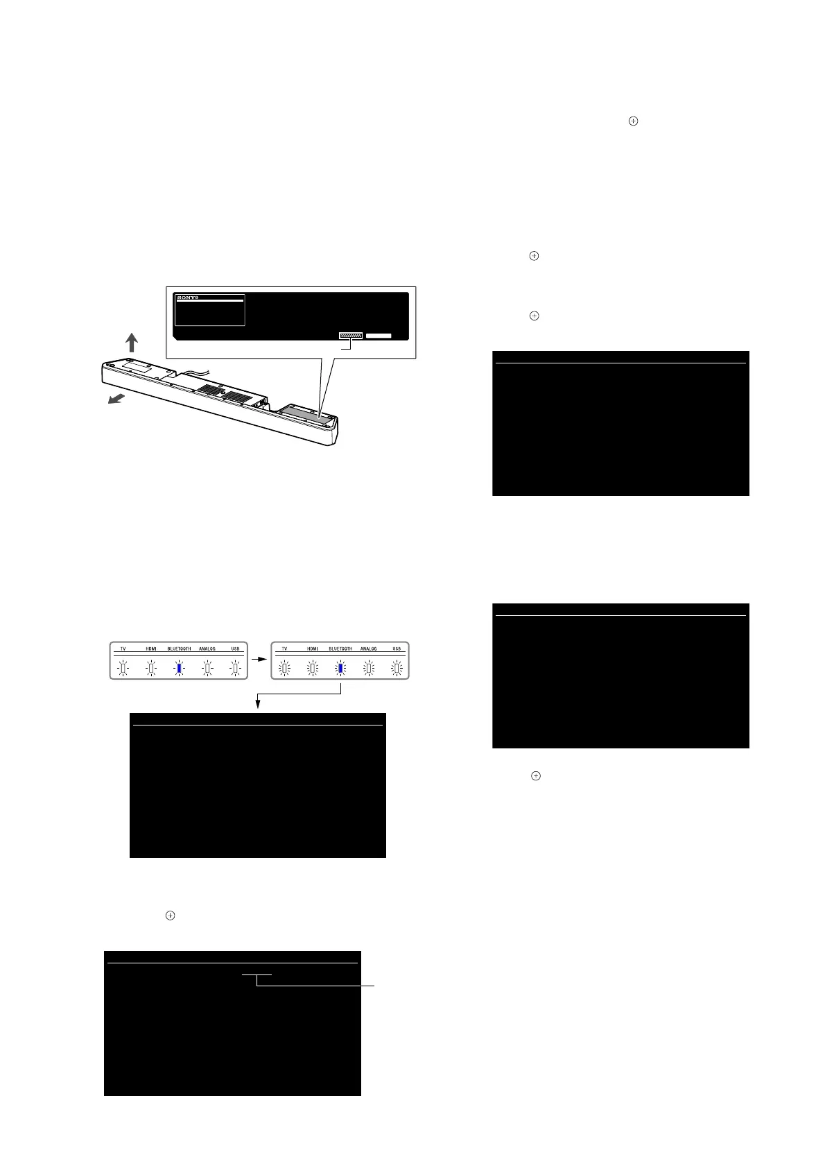
Describes button and LED locations for test modes.

FACTORY INITIALIZE

Resets all unit settings to their factory defaults.

USB UPDATE

Firmware update procedure using USB memory.

DEMO MODE OPERATIONS

Procedures for entering, customizing, and releasing demo mode.

PANEL TEST

Checking LED lighting state and key input.

SERVICE MODE SETUP

Setting up and using the service mode with a TV monitor.

TROUBLESHOOTING

PROTECTION MODE ISSUES

Troubleshooting steps when the protection mode is activated.

HDMI NO AUDIO/VIDEO OUTPUT

Diagnosing and resolving issues with HDMI audio and video output.

SOUND NOT OUTPUTTED

Troubleshooting steps when no sound is produced.

POWER NOT TURNED ON

Diagnosing and resolving power-on issues.

SOUND NOT OUTPUTTED OF ARC

Troubleshooting steps when ARC sound output is not working.

SUBWOOFER NOT LINKED

Diagnosing and resolving issues with subwoofer linking.

DIAGRAMS

HDMI SECTION BLOCK DIAGRAM

Block diagram of the HDMI section, showing signal paths.

MAIN SECTION BLOCK DIAGRAM

Block diagram of the main section, illustrating circuitry.

AMPLIFIER SECTION BLOCK DIAGRAM

Block diagram of the amplifier section, detailing signal flow.

PANEL/POWER SUPPLY BLOCK DIAGRAM

Block diagram of the panel and power supply circuitry.

PRINTED WIRING BOARDS AND SCHEMATICS

Layouts of printed wiring boards and schematic diagrams for key components.

EXPLODED VIEWS

FOOT SECTION

Exploded view of the foot section with parts list.

TOP CABINET SECTION

Exploded view of the top cabinet section with parts list.

BOTTOM CABINET SECTION

Exploded view of the bottom cabinet section with parts list.

MAIN BOARD SECTION

Exploded view of the main board section with parts list.

SK1 AMP BOARD SECTION

Exploded view of the SK1 AMP board section with parts list.

POWER BOARD SECTION

Exploded view of the power board section with parts list.

ELECTRICAL PARTS LIST

MAIN AND POWER BOARD PARTS

List of electrical components for the main and power boards.

SK1 AMP BOARD PARTS

List of electrical components for the SK1 AMP board.

ACCESSORIES AND CABLES

List of included accessories and cables.

Related product manuals