EasyManua.ls Logo

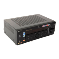
Sony STR-DE685 Service Manual

Sony STR-DE685
60 pages
To Next Page IconTo Next Page
To Previous Page IconTo Previous Page
Page #30 background imageLoading...
Page #30 background image
STR-DE685
3030
4-15. PRINTED WIRING BOARDS — DISPLAY SECTION — • Refer to page 22 for Circuit Boards Location and Common Note on Printed Wiring Boards.
1
A
B
C
D
E
F
G
H
I
234567891011121314
IC100
RV102
FL101
CNS100
S108
D102
R199
Q101
C108
C132
C133
C134
C135
C136
C137
C138
C139
C140
C141
C142
C143
R108
R112
R116
R131
R115
R114
R109
R111
R134
R133R132R135
R136
R117
R137
R113
R103
R102
R118
R101
R127
R125
C144
R122
R121
R126
R124
R123
Q107
Q106
Q100
CNP102
Q102
Q103
CNP103
R198
C109
C104
R165
R166
JW148
R167
R168
R142
R144
R143
JW140
JW130
R159
JW153
JW134
JW124
JW141
JW156
JW123
JW121
R106
JW139
Q111
Q110
Q109
Q108
R160
R163
JW154
R162
JW155
R104
IC102
R154
JW120
JW129
C100
C112
C110
C111
R150
C114
R169
C145
JW109
JW110
JW111
JW142
JW143
JW131
JW102
R161
JW119
JW147
JW146
JW118
R153
Q104
R148
C150
JW113
JW149
R141
JW128
JW127
JW132
JW133
JW115
JW104
JW105
JW157
JW136
JW137
JW125
JW117
JW145
R107
JW152
JW150
JW135
JW126
JW151
C101
L101
JW159
JW138
JW160
JW161
JW162
JW163
JW164
JW165
JW166
R105
R155
JW167
R170
R171
JW112
JW158
JW168
JW169
C155
C157
C156
L103
C151
L102
JW114
C158
C159
C160
IC101
R172
R173
R174
JW106
TP100
TP101
S112S116S131
S130 S115 S114 S109
S111
S110
S135
S113
S137
S132 S133
S117
S134
S136
S103
S123
S102
S107
S104
S105
S106
S124
S127 S101
S120
S122
S118
S100
S121
S126
C105
C115
D100
D110
D112
D111
D113
D114
D103
D105
D104
JW144
JW170
R175
JW101
RV101
CN101
S141
S142S138
S139
CN104
R138
R139
D100 B-6
D102 A-10
D103 E-8
D104 E-6
D105 E-7
D110 D-10
D111 D-10
D112 D-10
D113 D-9
D114 D-9
IC100 C-9
IC101 B-7
IC102 C-14
Q100 B-5
Q101 E-3
Q102 E-3
Q103 E-3
Q104 C-5
Q106 C-7
Q107 C-7
Q108 C-6
Q109 C-6
Q110 C-6
Q111 C-6
Semiconductor
Location
Ref. No. Location
(Page 27)
Ver 1.1

Other manuals for Sony STR-DE685

Question and Answer IconNeed help?

Do you have a question about the Sony STR-DE685 and is the answer not in the manual?

Sony STR-DE685 Specifications

General IconGeneral
Channels5.1
Total Harmonic Distortion0.09%
Power Output100 W per channel (8 ohms, 20 Hz - 20 kHz, 0.09% THD)
Tuning rangeAM/FM
Frequency response10 Hz - 100 kHz
Speaker load impedance8 ohms
Digital inputs1 x Optical, 1 x Coaxial
Video ConnectionsComposite video inputs

Summary

Audio Power Specifications

Power Output and Total Harmonic Distortion

Specifies RMS power output and total harmonic distortion for minimum power.

Amplifier Section Power Output

Details rated power output for stereo mode across different area codes.

Specifications Overview

Tuner Section Specifications

Safety Information

Safety Check-out and Leakage Test

Details safety checks, including AC leakage testing procedures and limits.

Safety-Related Component Warnings

Highlights critical components that are essential for safe operation.

Remote Control Operation

Disassembly Procedures

Test Modes

Diagrams

IC Pin Descriptions (IC1201 DSP) Part 1/2

Lists pin functions and descriptions for the DSP IC (part 1/2).

IC1201 Pin Descriptions (DSP) Part 2/2

Continues pin functions and descriptions for the DSP IC.

IC1601 Pin Descriptions (System Control) Part 1/2

Lists pin functions and descriptions for the System Control IC (part 1/2).

IC1601 Pin Descriptions (System Control) Part 2/2

Continues pin functions and descriptions for the System Control IC.

Block Diagrams

Tuner/Audio Section Block Diagram

Illustrates the signal flow within the tuner and audio processing sections.

Digital Section Block Diagram

Shows the signal paths and interconnections within the digital processing circuitry.

Key/Display Section Block Diagram

Illustrates the operation of the front panel controls and display elements.

Video Section Block Diagram

Depicts the signal flow and processing for video inputs and outputs.

Power Section Block Diagram

Shows the power supply distribution and regulation circuitry.

Circuit Boards Location and Waveforms

Circuit Diagrams and Layouts

Main Board Schematics and PWB

Provides printed wiring board layout and schematic diagrams for the main board.

Digital Board Schematics and PWB

Shows printed wiring boards and schematics for the digital section (parts 1 & 2).

Display Board Schematics and PWB

Presents printed wiring boards and schematics for the display section.

Video and S-Video Sections Schematics and PWB

Covers printed wiring boards and schematics for video, S-Video, and Speaker B sections.

Power Section Schematics and PWB

Provides printed wiring boards and schematics for the power supply section.

IC Block Diagrams

IC301/IC302 Component Video Board Diagrams

Block diagrams and pinouts for IC301 (multiplexer) and IC302 (amplifier) on the component video board.

Exploded Views

Electrical Parts List

Related product manuals