44
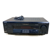
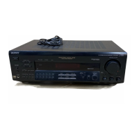
STR-DE685
SECTION 6
ELECTRICAL PARTS LIST
NOTE:
• Due to standardization, replacements in
the parts list may be different from the
parts specified in the diagrams or the
components used on the set.
• -XX and -X mean standardized parts, so
they may have some difference from the
original one.
• RESISTORS
All resistors are in ohms.
METAL:Metal-film resistor.
METAL OXIDE: Metal oxide-film resistor.
F:nonflammable
• Items marked “*” are not stocked since
they are seldom required for routine service.
Some delay should be anticipated
when ordering these items.
• CAPACITORS
uF : µF
• SEMICONDUCTORS
In each case, u : µ, for example:
uA.. : µA.. uPA.. : µPA..
uPB.. : µPB.. uPC.. : µPC.. uPD.. : µPD..
• COILS
uH : µH
Ref. No. Part No. Description Remark Ref. No. Part No. Description Remark
1-683-761-11 AC SELECT BOARD (E,JE)
****************
< CONNECTOR >
* CNP910 1-564-687-11 PIN, CONNECTOR 3P (E,JE)
< SWITCH >
0 S901 1-571-437-21 SWITCH, POWER VOLTAGE CHANGE
(VOLTAGE SELECTOR) (E,JE)
*************************************************************
A-4727-864-A COMPONENT VIDEO BOARD, COMPLETE
(US,CND)
A-4727-873-A COMPONENT VIDEO BOARD, COMPLETE
(EXCEPT US,CND,AEP,UK,AUS)
*********************************
< CAPACITOR >
C301 1-126-935-11 ELECT 470uF 20% 10V
(EXCEPT AEP,UK,AUS)
C302 1-126-935-11 ELECT 470uF 20% 10V
(EXCEPT AEP,UK,AUS)
C303 1-126-935-11 ELECT 470uF 20% 10V
(EXCEPT AEP,UK,AUS)
C308 1-126-964-11 ELECT 10uF 20% 50V
(EXCEPT AEP,UK,AUS)
C309 1-126-964-11 ELECT 10uF 20% 50V
(EXCEPT AEP,UK,AUS)
C310 1-126-964-11 ELECT 10uF 20% 50V
(EXCEPT AEP,UK,AUS)
C311 1-126-964-11 ELECT 10uF 20% 50V
(EXCEPT AEP,UK,AUS)
C312 1-126-964-11 ELECT 10uF 20% 50V
(EXCEPT AEP,UK,AUS)
C313 1-126-964-11 ELECT 10uF 20% 50V
(EXCEPT AEP,UK,AUS)
C317 1-126-947-11 ELECT 47uF 20% 25V
(EXCEPT AEP,UK,AUS)
C329 1-164-159-21 CERAMIC 0.1uF 50V
(EXCEPT AEP,UK,AUS)
C330 1-164-159-21 CERAMIC 0.1uF 50V
(EXCEPT AEP,UK,AUS)
C331 1-164-159-21 CERAMIC 0.1uF 50V
(EXCEPT AEP,UK,AUS)
C332 1-164-159-21 CERAMIC 0.1uF 50V
(EXCEPT AEP,UK,AUS)
C338 1-126-947-11 ELECT 47uF 20% 25V
(EXCEPT AEP,UK,AUS)
< CONNECTOR >
CNS301 1-569-299-11 SOCKET, CONNECTOR (L TYPE) 5P (US,CND)
CNS301 1-569-315-11 SOCKET, CONNECTOR 5P
(EXCEPT US,CND,AEP,UK,AUS)
< FILTER >
FB301 1-416-300-21 FILTER, NOISE (EXCEPT US,CND,AEP,UK,AUS)
FB302 1-416-300-21 FILTER, NOISE (EXCEPT US,CND,AEP,UK,AUS)
< IC >
IC301 8-759-231-66 IC TC74HC4053AP (EXCEPT AEP,UK,AUS)
IC302 6-701-891-01 IC NJM2581D (EXCEPT AEP,UK,AUS)
< JACK >
J301 1-816-359-11 JACK, PIN 9P (COMPONENT VIDEO DVD/LD IN,
VIDEO 2 IN,MONITOR OUT)
(EXCEPT AEP,UK,AUS)
< TRANSISTOR >
Q301 8-729-116-02 TRANSISTOR BA1A4M-TP
(EXCEPT AEP,UK,AUS)
< RESISTOR >
R301 1-247-804-11 CARBON 75 5% 1/4W
(EXCEPT AEP,UK,AUS)
R302 1-247-804-11 CARBON 75 5% 1/4W
(EXCEPT AEP,UK,AUS)
R303 1-247-804-11 CARBON 75 5% 1/4W
(EXCEPT AEP,UK,AUS)
R304 1-247-804-11 CARBON 75 5% 1/4W
(EXCEPT AEP,UK,AUS)
R305 1-247-804-11 CARBON 75 5% 1/4W
(EXCEPT AEP,UK,AUS)
R306 1-247-804-11 CARBON 75 5% 1/4W
(EXCEPT AEP,UK,AUS)
R307 1-247-804-11 CARBON 75 5% 1/4W
(EXCEPT AEP,UK,AUS)
R308 1-247-804-11 CARBON 75 5% 1/4W
(EXCEPT AEP,UK,AUS)
R309 1-247-804-11 CARBON 75 5% 1/4W
(EXCEPT AEP,UK,AUS)
R310 1-249-417-11 CARBON 1K 5% 1/4W
(EXCEPT AEP,UK,AUS)
R311 1-249-417-11 CARBON 1K 5% 1/4W
(EXCEPT AEP,UK,AUS)
•Abbreviation
CND : Canadian model
AUS: Australian model
JE : Tourist model
CH : Chinese model
MX : Mexican model
SP : Singapore model
MY : Malaysia model
TW : Taiwan model
AR : Argentina model
KR : Korean model
When indicating parts by reference
number, please include the board.
AC SELECT
The components identified by mark 0 or
dotted line with mark 0 are critical for
safety.
Replace only with part number specified.
Les composants identifiés par une marque
0 sont critiques pour la sécurité.
Ne les remplacer que par une piéce portant
le numéro spécifié.
COMPONENT VIDEO
Ver 1.1
 Loading...