2-15
PVM-14L1/14L1MDE/20L1
SSM-14L1/20L1
2-16. Adjustment of NTSC Mode
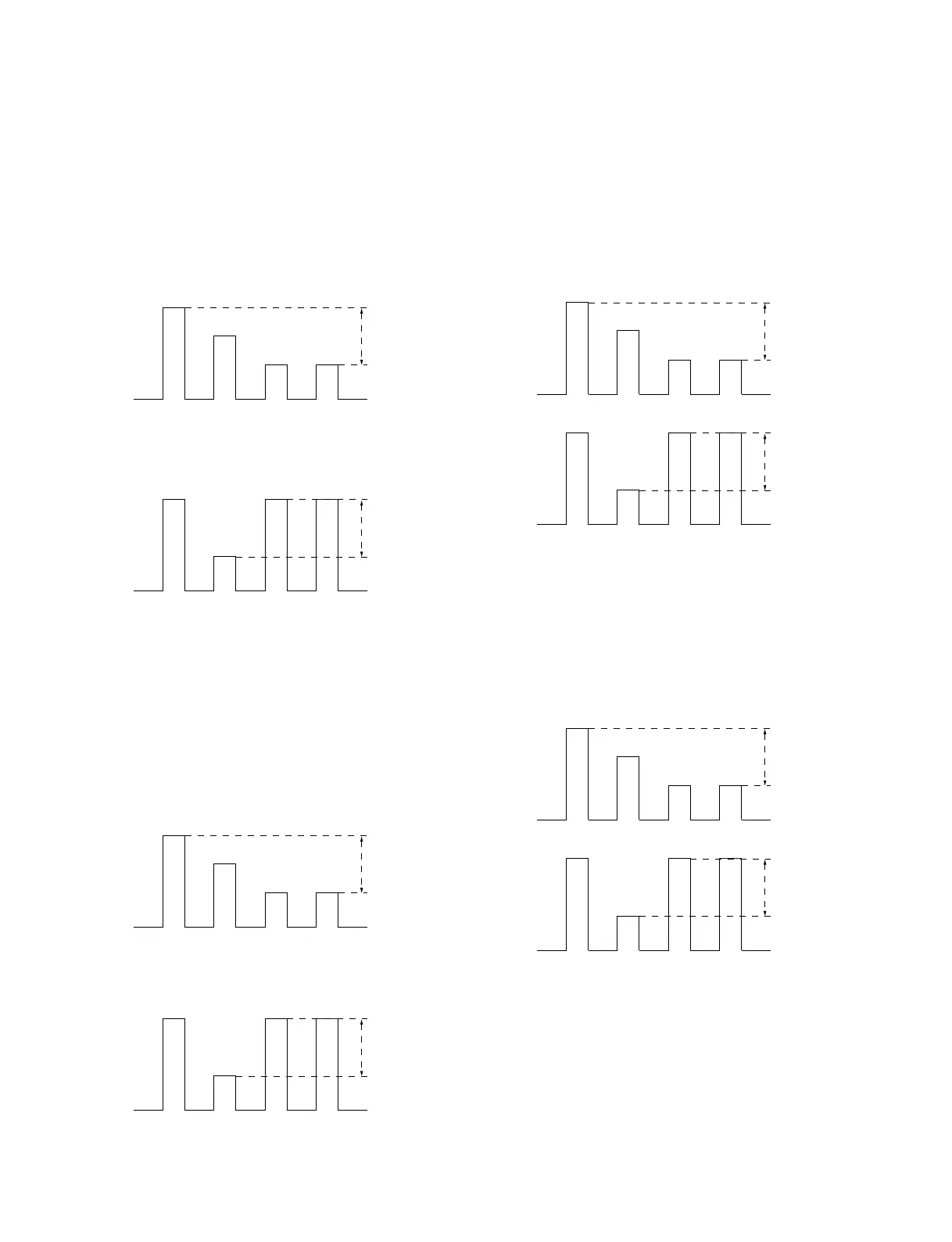
2-16-1. NTSC Composite Input
Input NTSC 75% color bar signal.
1. Adjust SUB CHROMA so that CN002-pin5 (JL053)
waveform A and D fall on same level.
2. Adjust SUB CHROMA so that CN002-pin5 (JL053)
waveform B and C fall on same level.
3. Repeat step 1 and 2, and adjust so that A, B, C, D fall
on same level.
2-16-2. NTSC Y/C Input
Input NTSC 75% color bar signal.
1. Adjust SUB CHROMA so that CN002-pin5 (JL053)
waveform A and D fall on same level.
2. Adjust SUB PHASE so that CN002-pin5 (JL053)
waveform B and C fall on same level.
3. Repeat step 1 and 2, and adjust so that A, B, C, D fall
on same level.
Less than 20 mV
Target; 0 mV
ABCD
Less than 20 mV
Target; 0 mV
ABCD
Less than 20 mV
Target; 0 mV
ABCD
Less than 20 mV
Target; 0 mV
ABCD
2-17. Adjustment of PAL Mode
2-17-1. PAL Composite Input
Input PAL 75% color bar signal.
1. Adjust SUB CHROMA so that CN002-pin5 (JL053)
waveform A and D fall on same level.
2-17-2. PAL Y/C Input
Input PAL 75% color bar signal.
1. Adjust SUB CHROMA so that CN002-pin5 (JL053)
waveform A from D fall on same level.
Less than 20 mV
Target; 0 mV
ABCD
Less than 20 mV
Target; 0 mV
ABCD
Less than 20 mV
Target; 0 mV
ABCD
Less than 20 mV
Target; 0 mV
ABCD
 Loading...