1-36 (E)
VPL-FHZ55
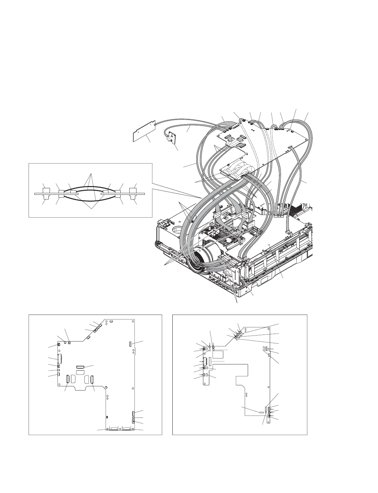
5. Attach the fi lter cover assembly. (Refer to Section 1-4-2.)
6. Connect the extension board, H board, NF board, and extension cables as shown in the fi gure.
n
. Secure the XC board to the main unit with the six screws.
. After the connecting with the C board and XC board, place the C board on the insulator and then
operate.
CN1701
CN1601CN1801
CN102 CN101
CN208
CN207
CN104
CN303
CN202
CN201
CN103
CN205
CN304
CN302
CN105
CN105
CN5105
CN204
CN301
CN106
CN204
CN5204
CN301
CN5301
CN106
CN5106
CN208
CN5207
CN5208
CN207
CN104
CN303
CN201
CN5201
CN5303
CN103
CN5103
CN5104
CN205
CN5205
CN5304
CN5302
CN304
CN302
I
J
F
A
B
B
B
CD
J
G
G
H
D
CN15 CN21
CN11 CN13
CN14 CN14 CN21
CN13 CN11
CN15
XC board
XC board (side A)C board (side A)
XF57 boards
X70 boards
NF board
H board
X70 boards
X70 boards
QA board
C board
For * marked connectors,
connect the harnesses which
were disconnected from C board.
*
*
*
*
*
*
*
*
* *
*
*
*
E FH
 Loading...