2-1 (E)
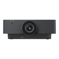
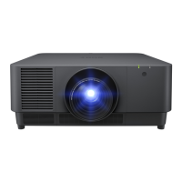
VPL-FHZ55
Section 2
Adjustments
2-1. Notes on Servicing
. The laser diode is used as a light source of this unit.
Never allow the light source to emit light with the cabinet removed.
Otherwise, it may cause damage to eyes or skin.
. Do not remove the lens when the set is lighting.
Otherwise, it may cause damage to eyes or skin.
. Do not release the protection switch with the cabinet removed.
Otherwise, the light source may suddenly start emitting light, causing damage to eyes or skin.
. In order to avoid inappropriate use of the laser diode, do not disassemble the laser unit assembly LEO.
2-1-1.
When the Optics Unit Assembly LEO or Prism Block Assembly is Replaced
1. Perform the V COM adjustment. (Refer to Section 2-3.)
2.
Write the Opt Unit data supplied with the prism assembly using Quick Access2. (Refer to Section 2-6-5.)
3. Perform the laser luminance and luminance sensor adjustment. (Refer to Section 2-4.)
2-1-2. When Replacing the C Board
1. Save the Opt Unit and NVM (All) data before replacement of the C board using Quick Access2.
(Refer to Sections 2-6-2 and 2-6-4.)
2. Replace the C board. (Refer to Section 1-4-4.)
3. Take notes of the following data in the C board after replacement.
Device → Panel Driver → 13 P.Drv/Volt Tune R, 14 P.Drv/Volt Tune G, 15 P.Drv/Volt Tune B.
4. Write the data saved in step 1 to replaced C board. (Refer to Sections 2-7-5 and 2-7-7.)
5. Enter the data taken notes in step 3.
6. Select the menus: Device → Save To Memory, then select [Yes] and press [ENTER].
7. Perform the V COM adjustment. (Refer to Section 2-3.)
8. Perform the laser luminance and luminance sensor adjustment. (Refer to Section 2-4.)
9. Perform the Ext (Network) reset. (Refer to Section 2-5-5.)
2-1-3. Parts That Require Adjustment of Laser Luminance and Luminance Sen-
sor When They are Replaced
When replacing the following parts, perform “2-4. Adjustment of Laser Luminance and Luminance
Sensor”.
. Prism block assembly (Refer to Section 2-1-1.)
. C board (Refer to Section 2-1-2.)
. Laser unit assembly LEO
. Optics unit assembly LEO (Refer to Section 2-1-1.)
. Parts in optics unit assembly LEO
. SA board
. SB board
. Lens
 Loading...