2
WM-GX400
Flexible Circuit Board Repairing
• Keep the temperature of the soldering iron around 270°C during
repairing.
• Do not touch the soldering iron on the same conductor of the
circuit board (within 3 times).
• Be careful not to apply force on the conductor when soldering
or unsoldering.
Notes on chip component replacement
• Never reuse a disconnected chip component.
• Notice that the minus side of a tantalum capacitor may be dam-
aged by heat.
TABLE OF CONTENTS
SECTION 1
GENERAL
This section is extracted from
instruction manual.
Specifications ........................................................................... 1
1. GENERAL
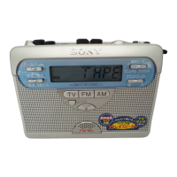
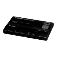
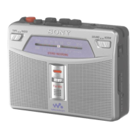
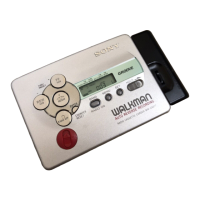
Location of Parts and Controls .......................................... 2
2. DISASSEMBLY
2-1. Cabinet (Front)Cabinet (Rear),
"Lid, Cassette ASSY" ............................................... 3
2-2. Main Board ................................................................. 4
2-3. Mechanism Deck ........................................................ 4
2-4. HRPE301 (REC/PB/ERASE head),
M601 (Capstan/reel motor), Belt (AR) ....................... 5
2-5. Display Board ............................................................. 5
3. ADJUSTMENTS
3-1. Mechanical Adjustments ............................................. 6
3-2. Electrical Adjustments ................................................ 6
4. DIAGRAMS
4-1. Explanation of IC Terminals ....................................... 7
4-2. Block Diagrams –Tape Section– ................................ 8
4-3. Block Diagrams –Tuner Section– ............................... 9
4-4. Printed Wiring Board –Main Section (Side A)– ....... 10
4-5. Printed Wiring Board –Main Section (Side B)– ....... 11
4-6. Schematic Diagram –Main Section (1/2)– ............... 12
4-7. Schematic Diagram –Main Section (2/2)– ............... 13
4-8. Printed Wiring Board –Display Section (Side A)– ... 14
4-9. Printed Wiring Board –Display Section (Side B)– ... 15
4-10. Schematic Diagram –Display Section– .................. 16
5. EXPLODED VIEWS
5-1. Cabinet (Rear) Section .............................................. 20
5-2. Cassette Lid Section ................................................. 21
5-3. Mechanism Section-1 (MT-WMGX400-175) .......... 22
5-4. Mechanism Section-2 (MT-WMGX400-175) .......... 23
6. ELECTRICAL PARTS LIST ................................ 24
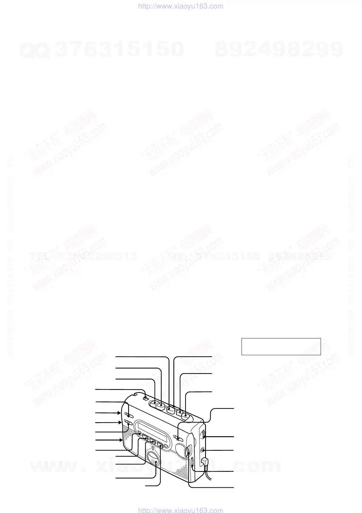
Location of parts and controls
PAUSE
z REC
DIR
REC TIME
AVLS
ISS
DC IN 3V
SPEAKER
i
x STOP
FF/CUE
REW/REVIEW
VOL
FM
AM
OFF
TUNING MODE
TUNING
MIC (PLUG IN POWER)
ENTER
built-in microphone
FM MODE
z
ST/MONO
FM MODE
z
DX/LOCAL
(or/ou/oder)
Y PLAY
w
w
w
.
x
i
a
o
y
u
1
6
3
.
c
o
m
Q
Q
3
7
6
3
1
5
1
5
0
9
9
2
8
9
4
2
9
8
T
E
L
1
3
9
4
2
2
9
6
5
1
3
9
9
2
8
9
4
2
9
8
0
5
1
5
1
3
6
7
3
Q
Q
TEL 13942296513 QQ 376315150 892498299
TEL 13942296513 QQ 376315150 892498299
http://www.xiaoyu163.com
http://www.xiaoyu163.com
 Loading...