471
Settings Relating to
Function Links
Setting a Cross-Point Button Link
This configures the bus link function that links together
two buses within the switcher.
Setting a bus link
1
In the Engineering Setup >Switcher >Link menu
(7336), press [Internal Bus Link].
The Internal Bus Link menu (7336.1) appears.
2
Select the target link number to set.
3
Press [Link Bus Select].
The Link Bus Select menu (7336.2) appears.
The bottom of the status area shows a list of selectable
buses.
4
In the <Bus Select> group, select [Master Bus] (link
source).
5
Select the bus for the link source, and press [Bus Set].
M/E-1 to 5 Trans PGM and P/P Trans PGM can be set
only when [Master Bus] is selected.
When one of M/E-1 to M/E-5 Trans PGM or P/P Trans
PGM is selected for [Master Bus], the link setting
becomes effective as soon as you start moving the
fader lever.
6
In the <Bus Select> group, select [Linked Bus] (link
destination).
7
Select the bus for the link destination, and press [Bus
Set].
AUX1 to 48 as Key can be set only when [Linked Bus]
is selected.
8
Select the link table number, and press [Link Table
Set].
To release the link
In the Engineering Setup >Switcher >Link >Internal Bus
Link menu (7336.1), select a link number and press
[Clear].
Setting a link table
1
In the Engineering Setup >Switcher >Link >Internal
Bus Link menu (7336.1), select the target link number
to set.
2
Press [Link Table Select].
The Link Table Select menu (7336.3) appears.
The bottom of the status area shows a list of the
selected link table signals.
3
Select the link source and link destination signals.
4
Press [Link Src Set].
To initialize the link table setting
Press [Init Link Table], check the message, then press
[Yes].
To select another link table
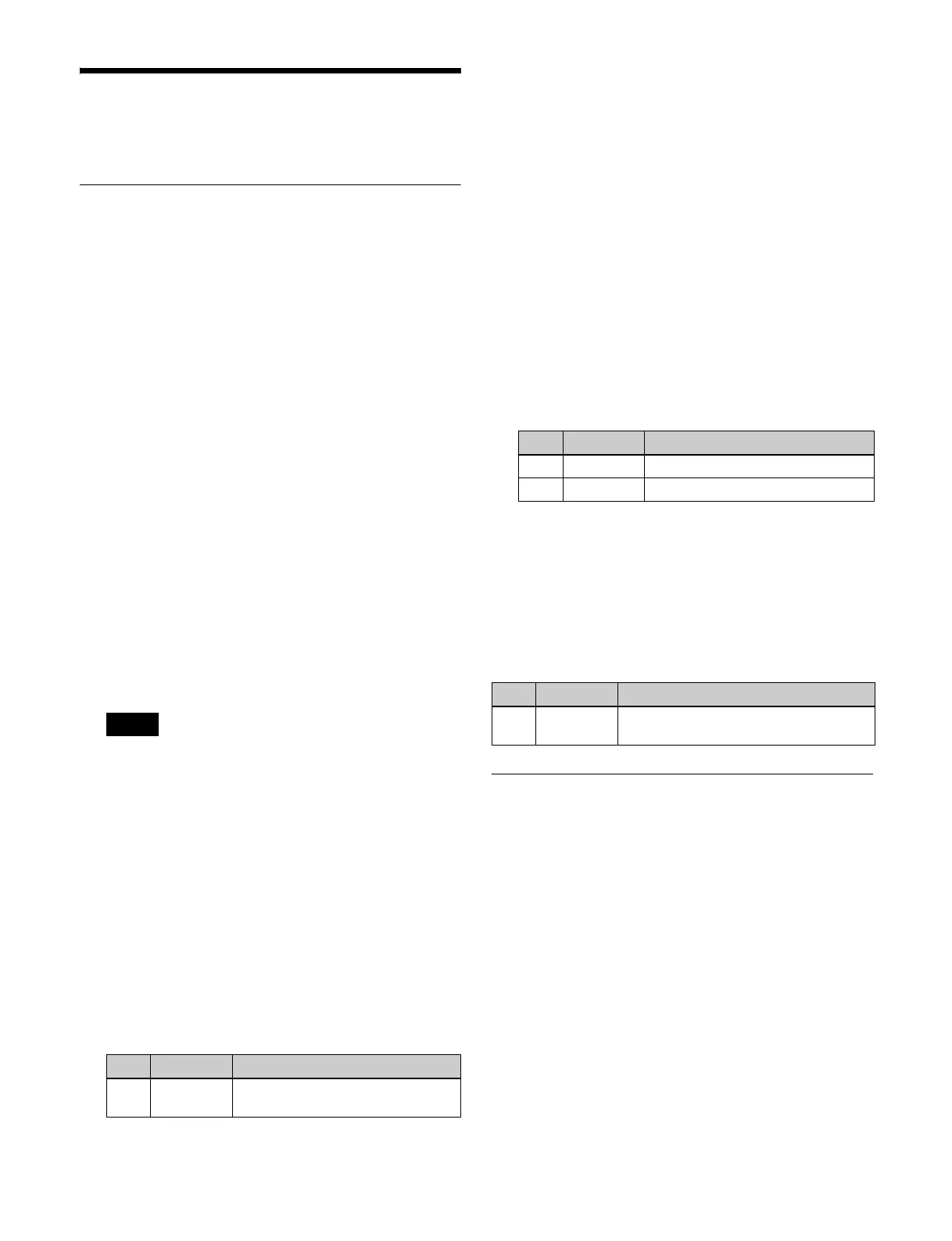
Select the link table number using the following
parameter, and press [Link Table Set].
Setting a Link Between M/E Banks
The operations which can be linked are as follows.
• Transition execution (auto transition, cut, and fader lever
operation)
• Next transition selection
• Transition type selection
1
In the Engineering Setup >Switcher >Link menu
(7336), press [M/E Link].
The M/E Link menu (7336.6) appears.
The status area shows the link number list on the left
and a list of the switcher banks (M/E or P/P) that can
be selected on the right.
2
Select the target link number to set.
3
In the <M/E Select> group, select [Master M/E] (link
source).
Note
No. Parameter Adjustment
3Link Table
No
Link table number
No. Parameter Adjustment
4 Main No Video/key signal for link source
5 No Video/key signal for link destination
No. Parameter Adjustment
3Link Table
No
Link table number
 Loading...