6.2.3 Limitations and hardware configuration - JTAG (CN14) or MIPI10 (CN16)
Limitations: STM32H7B3LIH6QU JTAG cannot be connected at the same time to STLINK-V3E and to CN14 or
CN16 connector. To be able to use JTAG on CN14 or CN16 connector, it is necessary to disconnect JTAG signals
from STLINK-V3E (JTMS, JTCK, JTDO, and NRST).
• To do so, R409, R401, R399, and R398 must be removed.
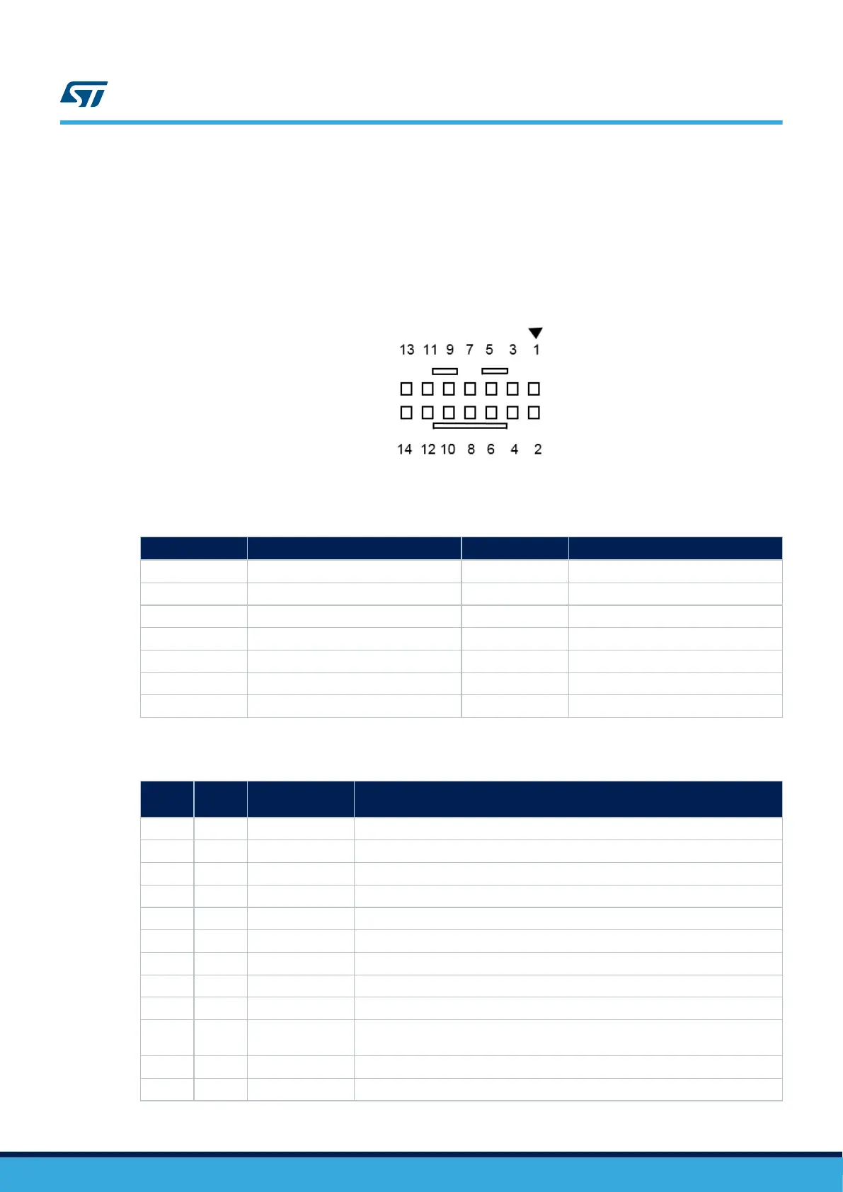
6.2.4 Interface
Figure 6. STDC14 / MIPI10 debugging connector CN16
Table 5. STDC14 / MIPI10 debugging connector CN16
Pin number Description Pin number Description
1 (STDC14) NC 2 NC (STDC14)
3 (MIPI10) +3.3V 4 (MIPI10) SWDIO-TMS / PA13
5 (MIPI10) GND 6 (MIPI10) SWCLK-TCK / PA14
7 (MIPI10) GND 8 (MIPI10) SWO-TDO / PB3
9 (MIPI10) KEY (NC) 10 (MIPI10) TDI / PA15
11 (MIPI10) GNDDetect 12 (MIPI10) RESET#
13 (STDC14) VCP_USART_RX / PB14 or PA2 14 (STDC14) VCP_USART_TX / PB15 or PA3
Table 6. STDC14 / MIPI10 debug connector CN16
MIPI10
pin
STDC14
pin
CN16 Designation
- 1 NC Reserved
- 2 NC Reserved
1 3 T_VCC Target VCC
2 4 T_SWDIO Target SWDIO using SWD protocol or Target JTMS (T_JTMS) using JTAG protocol
3 5 GND Ground
4 6 T_SWCLK Target SWCLK using SWD protocol or Target JCLK (T_JCLK) using JTAG protocol
5 7 GND Ground
6 8 T_SWO Target SWO using SWD protocol or Target JTDO (T_JTMS) using JTAG protocol
7 9 KEY (NC) KEY (NC)
8 10 T_JTDI
Not used by SWD protocol, Target JTDI (T_JTDI) using JTAG protocol, only for
external tools
9 11 GNDDetect GND detect for plug indicator, used on SWD and JTAG neither
10 12 T_NRST Target NRST using SWD protocol or Target JTMS (T_JTMS) using JTAG protocol
UM2662
External JTAG, SWD, and trace
UM2662 - Rev 1
page 13/95

 Loading...


