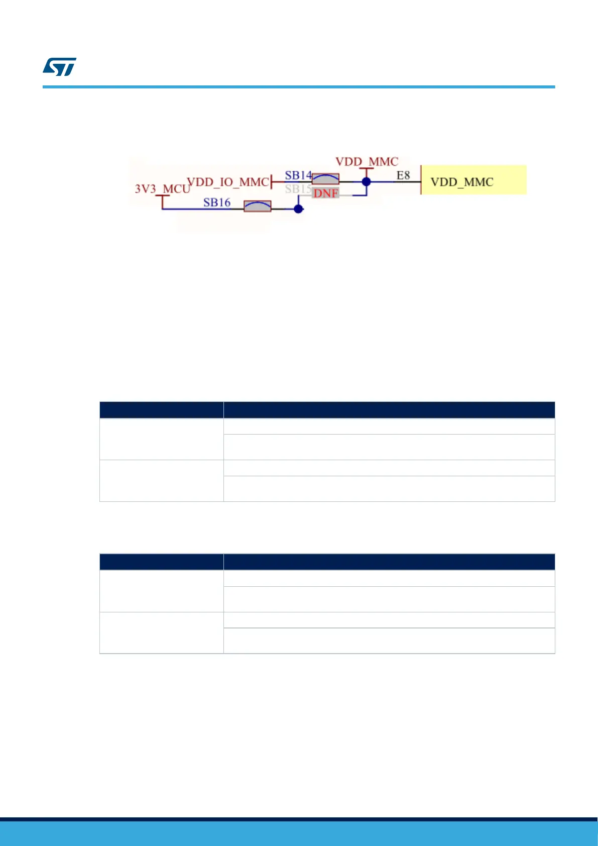
Figure 21. VDDMMC schematic (Page 9)
6.4 Clock, reset, and boot
6.4.1 Clock source
Two clock sources are available on the STM32H7B3I-EVAL Evaluation board for STM32H7B3LIH6QU and its
embedded RTC, and other clock sources for their peripherals.
• 24 MHz crystal X1 for the STM32H7B3LIH6QU microcontroller. It can be disconnected by removing R20 and
R21 when the internal RC clock is used.
• 32.768 kHz crystal X2 for embedded RTC
• 24 MHz oscillator X3 for USB OTG HS PHY
Table 16. 24 MHz crystal X1 related solder bridges
Solder bridge
Description
(1)
SB7, R21
PH0 is connected to 24 MHz crystal when R21 is fitted and SB7 open.
PH0 is connected to extension connector CN6 when SB7 is closed. In such a case, R21
must be removed to avoid disturbance due to the 24 MHz quartz
SB6, R20
PH1 is connected to 24 MHz crystal when R20 is fitted and SB6 open.
PH1 is connected to extension connector CN6 when SB6 is closed. In such case, R20
must be removed to avoid disturbance due to the 24 MHz quartz
1. The default setting is in bold.
Table 17. 32.768 kHz crystal X2 related solder bridges
Solder bridge
Description
(1)
SB8, R23
PC14 is connected to 32.768 kHz crystal when R23 is fitted and SB8 is open.
PC14 is connected to extension connector CN5 when SB8 is closed. In such case R23
must be removed to avoid disturbance due to the 32 Khz quartz.
SB9, R24
PC15 is connected to 32.768 kHz crystal when R24 is fitted and SB9 is open.
PC15 is connected to extension connector CN5 when SB9 is closed. In such case R24
must be removed to avoid disturbance due to the 32 Khz quartz.
1. The default setting is in bold.
UM2662
Clock, reset, and boot
UM2662 - Rev 1
page 27/95

 Loading...


