Jumper
Description
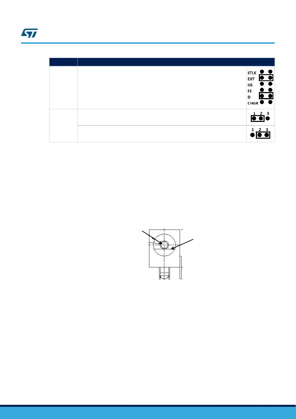
(1)
JP29
For power supply from power supply jack (CN17) to both STM32H7B3I-EVAL and the
daughterboard connected on CN5 and CN6, JP29 is set as shown on the right.
The daughterboard must not have its own power supply connected.
JP37
V
bat
is connected to +3.3V when JP37 is set as shown on the right.
V
bat
is connected to the battery when JP37 is set as shown on the right.
1. The default setting is in bold.
The LED LD7 is lit when the STM32H7B3I-EVAL Evaluation board is powered by the 5V correctly.
Note: In order to avoid the impact of USB PHY and get precise results of current consumption on JP3, the following
caution must be taken into account.
1. Configure USB HS PHY into Low Power Mode (Register Address=04, bit 6 in USB PHY).
The STM32H7B3I-EVAL Evaluation board can be powered from a DC 5V power supply via the external power
supply jack (CN17) shown in Figure 9. The central pin of CN17 must be positive.
Figure 9. Power supply connector CN17
DC +5V
GND
UM2662
Power supply
UM2662 - Rev 1
page 18/95

 Loading...


