– 123 –
APPENDIX
Appendix D: Serial Interface
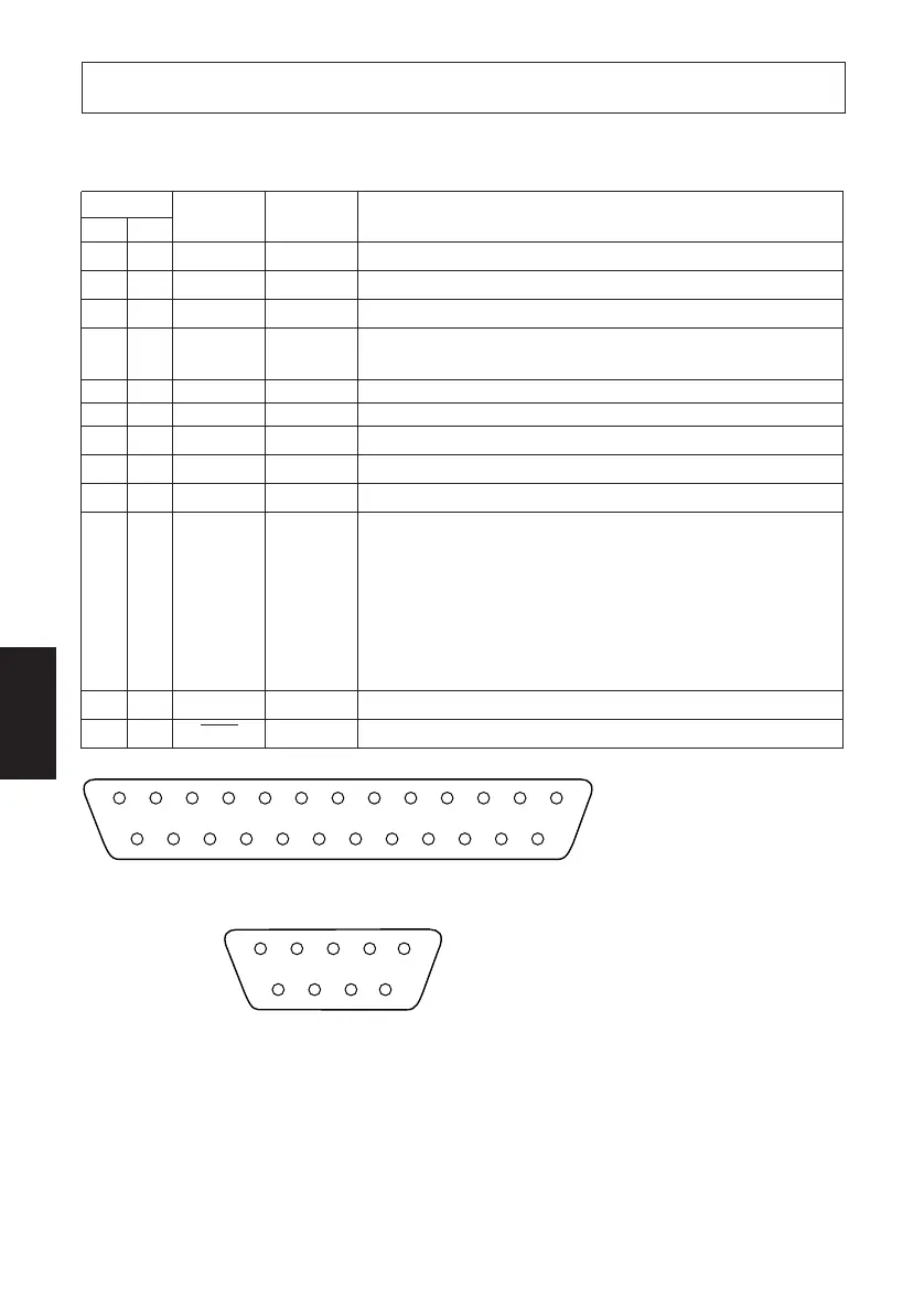
D-1. RS-232C Connector
Pin No.
Signal name
Direction Function
25 Pin
9 Pin
1 F-GND — Frame ground
2 3 TXD OUT Transmission data
3 2 RXD IN Receive data
4 7 RTS OUT Request To Send: The printer sets this signal to “SPACE” when it
is ready to send.
5 N/C Not used
8 CTS IN Status of this signal is not checked.
6 6 DSR IN Status of this signal is not checked.
7 5 S-GND — Signal ground
8~19 1,9 N/C Not used
20 4 DTR OUT Indicates whether data receive from host is enabled or disabled.
DTR/DSR Communication Mode
Space when receive is enabled.
X-On/X-Off Communication Mode
Always space, except during following conditions:
• Period between reset and communication enabled
• During self-test printing
21~24
N/C Not used
25 INIT IN Not used
13
25
1
14
5
9
1
6
D-Sub 25 pin
D-Sub 9 pin
 Loading...