37MS 290, MS 310, MS 390
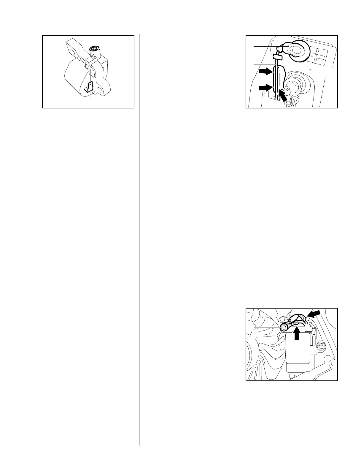
The ignition module accommodates
all the components required to
control ignition timing. There are
two electrical connections on the
coil body:
: High voltage output for ignition
lead (1)
209RA112
2
1
VA
: Connector tag (2) for the short
circuit wire
Testing in the workshop is limited to
a spark test.
A new ignition module must be
installed if no ignition spark is
obtained (after checking that wiring
and stop switch are in good
condition)..
Ignition timing is fixed and cannot
be adjusted during repair or
servicing work
Since there is no mechanical wear
in these systems, ignition timing
cannot get out of adjustment as a
result of wear.
– Remove the handle housing,
b 9.2
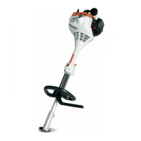
: Pull the spark plug boot (1) off the
spark plug.
: Pull ignition lead (3) out of
retainer (2).
209RA109
2
VA
3
1
: Pull the ignition lead (3) out of the
guide (arrows).
: Take out the screw (1) and
remove the ground wires
(arrows).
209RA113
VA
1
7.1 Ignition Module 7.1.1 Ignition Timing 7.1.2 Removing and Installing
 Loading...