Original assembly/operating instructions Gear limit switch Type series 51 • No. 151-00004 H • 01.2018 17
4.1.4 General information, GCLS type series 51
The gear parts of the GCLS can be damaged by ozone concentrations above normal threshold values
(Regulation 2008/50/EC); in particular in the direct vicinity of circuit breakers (ozone formation through
electricarcs), the GCLS may only be used if it is protected accordingly (min. IP54).
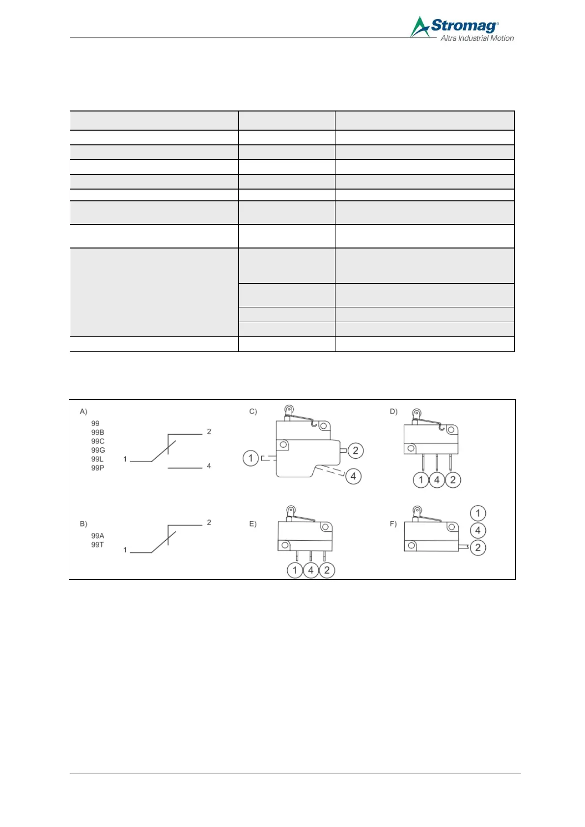
4.1.5 Specific electrical values and position of the contact
A Changeover circuit D Flat plug
B Circuit breaker/switch E Soldering pins
C - F Position of the contact connectors F Stranded wire output (1 = black, 4 = blue,
2 = grey)
C Screw connection
Information Value Comment
Operating life of the contact 10.000.000 Mechanical circuits
Operating time 100% Suitable for continuous operation
Max. speed 1.000 to 1.800 rpm Dependent on the frame size
Min. speed 0,67 to 1415 rpm Dependent on the frame size
Radial force drive 9 to 82 N
depending on the speed and the ambient
depending on the speed and the ambient
temperature, see section 4.1.7
Ambient temperature -40 to +80 °C
For cUL approval, the max. ambient
temperature is 50° C.
Without housing (without protection against
accidental contact with voltages <25 V AC
or 60 V DC with plug connections)
Without housing (contact on the circuit
board or with protection against accidental
Aluminium housing (design B3/B14)
Plastic housing (design B3/B14/B5)
Max. permissible relative humidity 0 to 60 %