6.3 Assembly mechanics
Before assembly of the GCLS, the machine must be suitably positioned so that the installation space is easily
accessible.
NOTE
GCLS with a preset switching position are provided with a transport lock.
The lock may only be removed directly before assembly. For assembly, the machine must be located
in the corresponding predefined position.
NOTE
When driving screws into the machine-side threads, the following can be obtained from the operating
instructions of the machine:
Screw tightening torques,
Screw locking agent to be used, if necessary.
NOTE
The installation space must be and remain dust-free and dry.
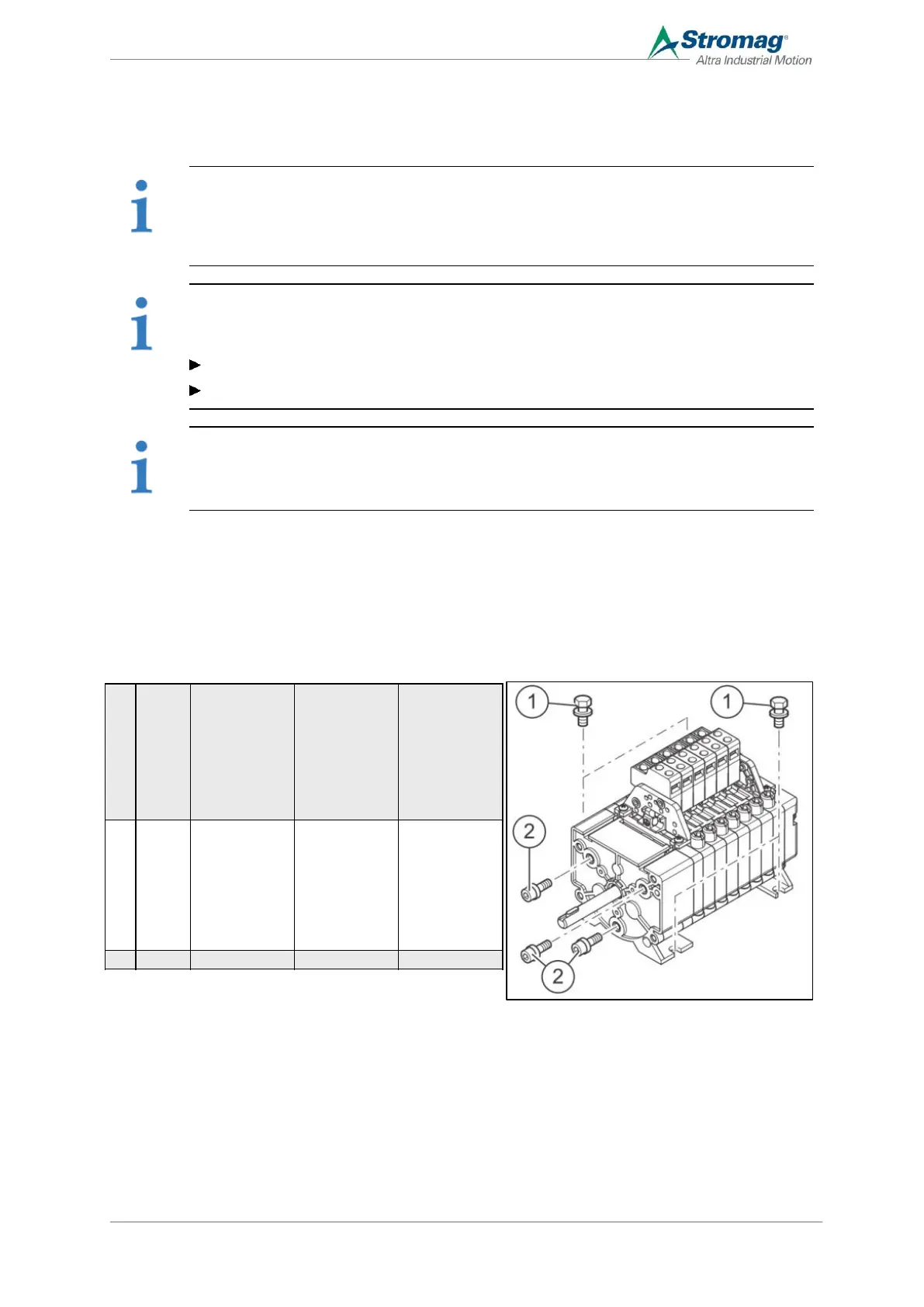
6.3.1 Assembly design IP20 (without housing)
Mount the GCLS on the machine
1. The connection between the drive shaft of the GCLS and the machine must be positively locked.
2. Depending on the installation conditions: Mount the GCLS on the housing or input side using screws.
3. Adjust switching points, see chapter 6.6.2Fehler!
Verweisquelle konnte nicht gefunden werden..