Original assembly/operating instructions Gear limit switch Type series 51 • No. 151-00004 H • 01.2018 25
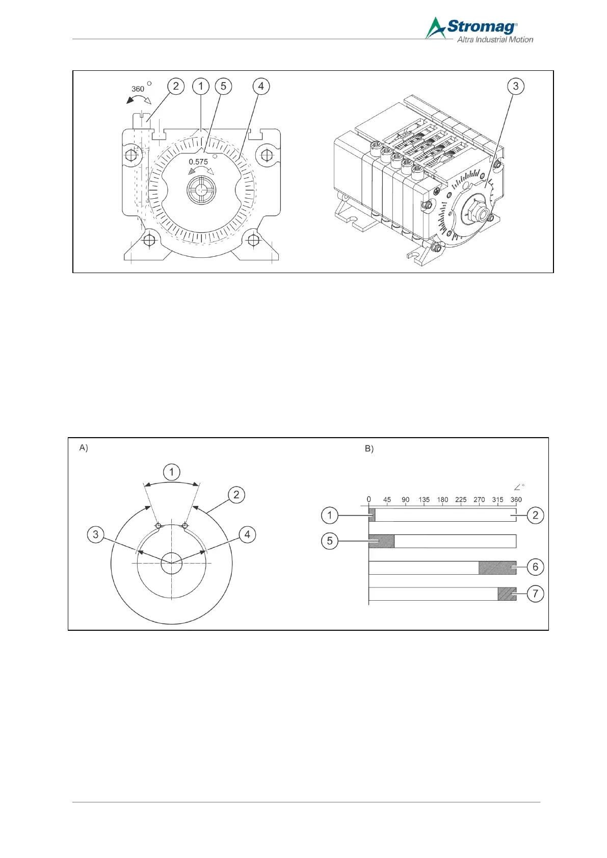
Indicator disc/dial (optional) for the block adjustment display
1 Cam disc 4 Dial, 5° separation
2 Adjustment worm of the final cam disc 5 Indicator
3 Indicator disc (optional)
By means of one of the indicator discs (3) attached to the back (B-side) of the GCLS, the block adjustment setting
can be read from the dial (4) on the back panel. The indicator disc rotates in parallel to the cam discs. After
adjusting the final cam disc, the indicator (5) should be placed at zero. The indicator disc is clamped and can be
rotated by hand.
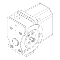
5.3.3 Special cam discs
A Cam angle diagram B Application examples
1 Effective cam angle α (=castor angle) 1 Effective cam angle 15°
2 Effective cam angle β 5 Effective cam angle 60°
3 Switching point radius 6 Effective cam angle 90°
4 Reset point radius 7 Effective cam angle 45°