EasyManuals Logo
Home>Stromag>Switch>51 Series

Stromag 51 Series User Manual

Default Icon
44 pages
To Next Page IconTo Next Page
To Previous Page IconTo Previous Page
Page #31 background imageLoading...
Page #31 background image
Original assembly/operating instructions Gear limit switch Type series 51 • No. 151-00004 H • 01.2018 31
Item no.
Number of
screws
Position
Screws
Tightening
torque
(3) 4
Housing
side
see operat-
ing instruc-
tions of the
machine.
see operat-
ing instruc-
tions of the
machine.
(4) 3 Input side
M5, 9 mm
deep
5 Nm
Item no.
Number of
screws
Position
Screws
Tightening
torque
(2) 3 Input side
M6, 8 mm
deep
2.5 Nm
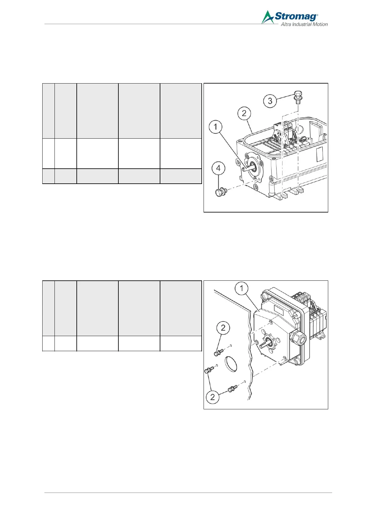
6.3.2 Housing assembly, IP65
Mount the GCLS on the machine
1. The connection between the drive shaft (1) of the GCLS and the machine must be positively locked.
2. Depending on the installation conditions: Mount the GCLS on the housing or input side using screws
3. For adjusting switching points, see section 6.6.2.
4. Mount the housing cover, see section 6.7.
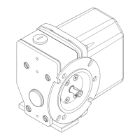
6.3.3 Housing assembly, IP66
Mount the GCLS on the machine
1. The connection between the drive shaft of the GCLS and the machine must be positively locked.
2. Mount the GCLS (1) with screws.GCLS maschinenseitig montieren
3. For adjusting switching points, see section 6.6.2.
4. Mount the housing cover, see section 6.7.
Fig. 14
Fig. 15

Table of Contents

Questions and Answers:

Stromag 51 Series Specifications

General IconGeneral
BrandStromag
Model51 Series
CategorySwitch
LanguageEnglish

Related product manuals