Original assembly/operating instructions Gear limit switch Type series 51 • No. 151-00004 H • 01.2018 34
6.4.3 Connect the flat plug
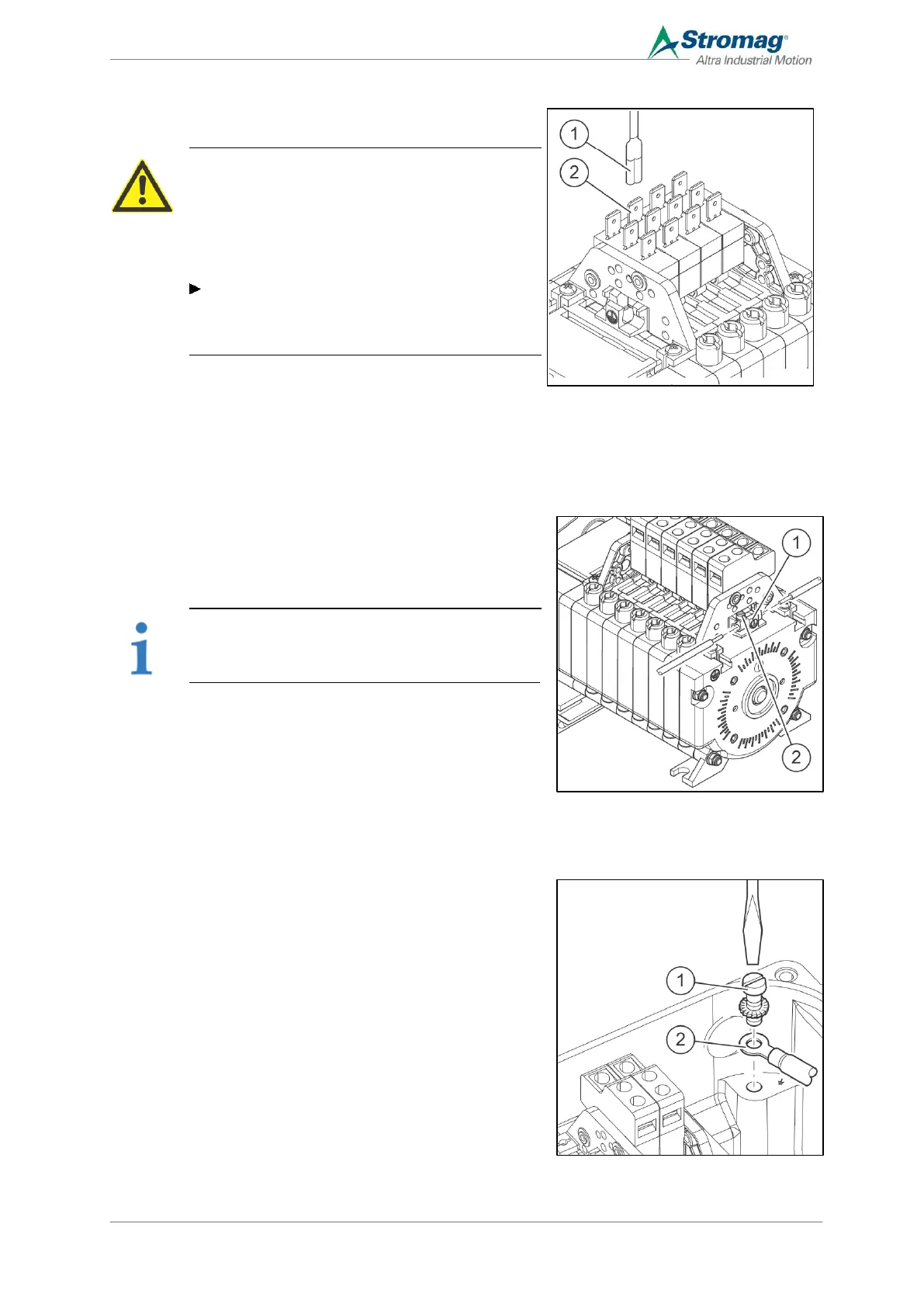
Connection with flat plug
CAUTION
Risk of accidents caused by live components
For contacts with a flat plug connection and voltages
over 25 V/AC or 60 V/DC, fully insulated flat plugs must
be used by the customer as a protection against
accidental contact.
If only the NC function is required for the
changeover contacts, the NO connection that is not
required must also be provided with a flat plug sleeve
as a protection against accidental contact.
1. Prepare the ends of the connecting cables with a flat plug,
6 mm (1).
2. Fit the cable and check that it is securely seated
6.4.4 Connect the earth conductor for IP66 housings
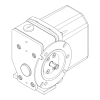
Earth conductor connection
An earth conductor of up to 1.5 mm
2
(min. wire crosssection of the
connecting cable) can be connected and looped via a bridge
connection (1) on the rear contact carrier.
NOTE
This design is only required for the CSA and cUL
market.
1. Strip the ends of the earth conductors by approx. 6 mm.
2. Plug the cable in and tighten the screws (2) [1 Nm].
6.4.5 Connect the earth conductor for IP65 housings
Earth conductor connection
1. Strip the ends of the earth conductors by approx. 6 mm.
Provided with a ring terminal end (2), if necessary.
2. Fit the cable and tighten the screw (1) [2.5 Nm].