25
4
Communication
Connection
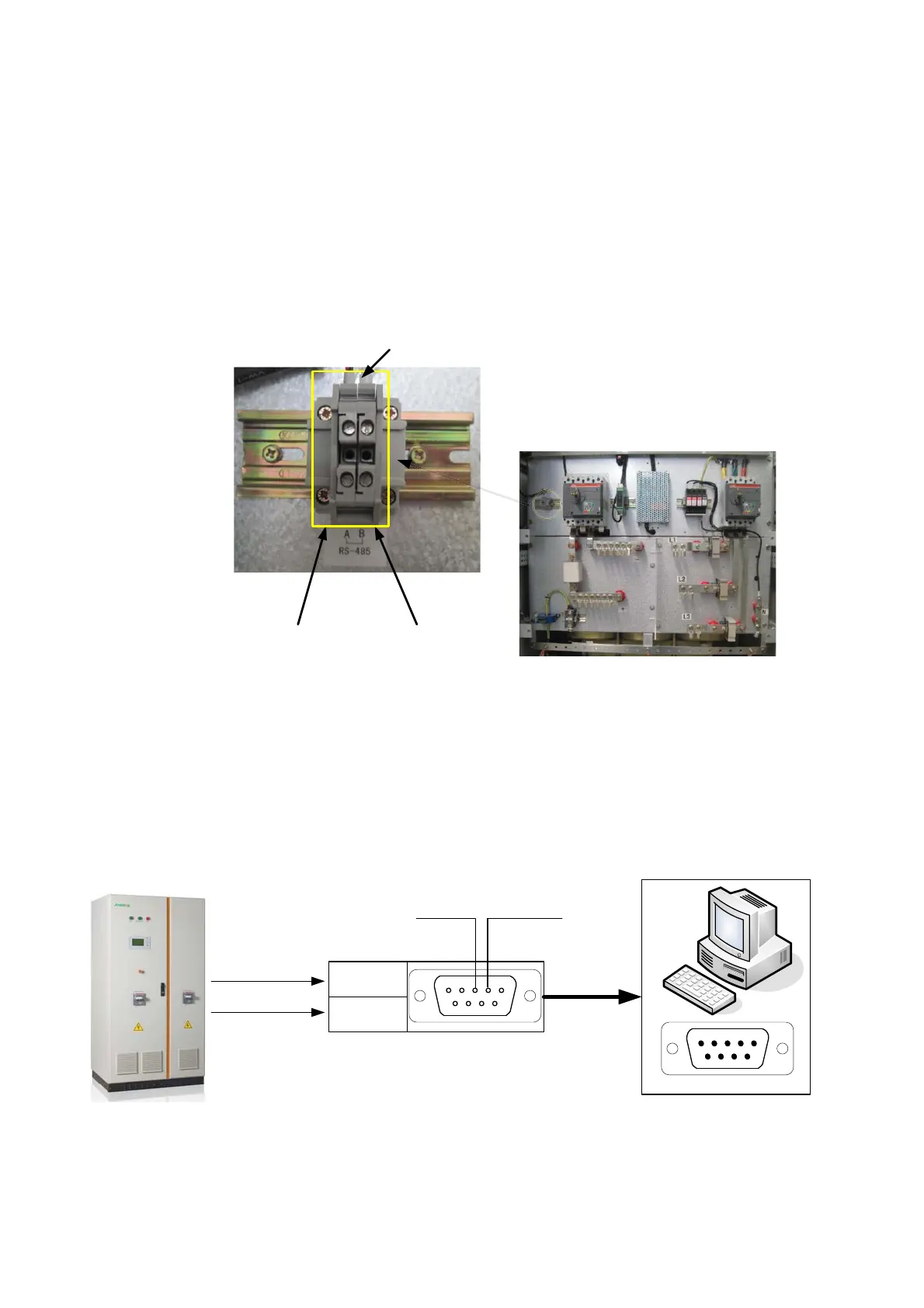
4.6.1.
Identify the RS485 Terminals
1. Route the communication wires through the cable entry holes.
2. Connect the wires to the RS485 A/B terminals respectively, see
Figure 4-9.
56$
56%
&RPPXQLFDWLRQ7HUPLQDOV
Figure 4-9 Serial communication wire routing
Connect RS485 Wires to a PC through RS485/232 Converter
1. Route the RS485A wire to the RS485/232 converter TX+ or RX+.
2. Route the RS485B wire to the RS485/232 converter TX- or RX-.
3. Secure the wires are tightened.
4. Connect the RS485/232 converter DB9 to the PC DB9 serial port.
RS485A
RS485B
TX+/RX+
TX-/RX-
543
2
1
9
87 6
PIN3:TXD PIN2:RXD
RS485/232 Converter
SG100K3
PC RS232 Port
Figure 4-10 Serial communication interface connection
 Loading...