28
The cable colors in figures in this manual are for reference only. Please select ca-
bles according to local cable standards.
5.2 Terminal Description
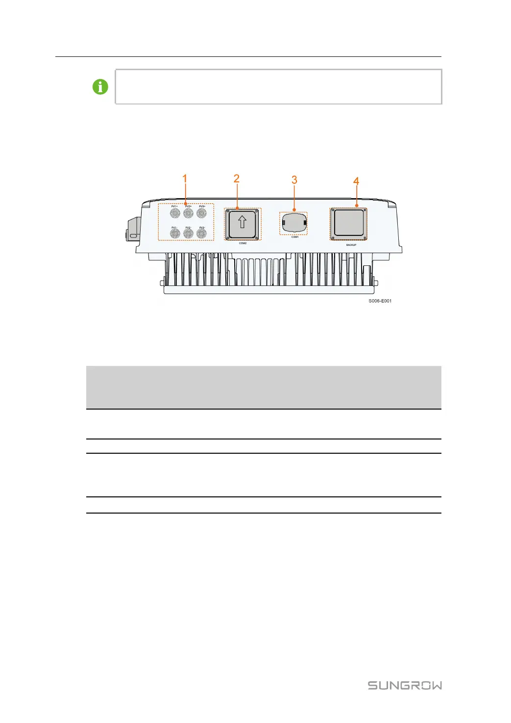
All electrical terminals are located at the bottom side of the inverter.
figure 5-1 Terminals
* The image shown here is for reference only. The actual product received may differ.
table 5-1 Terminal Description
No. Name
Description
Decisive Volt-
age
Classification
1
PV1+, PV1–, PV2+,
PV2–, PV3+, PV3–
The terminal number depends on in-
verter model.
DVC-C
2 COM2 / /
3 COM1
Communication accessory port to be
connected to WiFi—P2 communica-
tion module.
DVC-A
4 GRID
AC terminal to connect to the grid.
DVC-C
5.3 Electrical Connection Overview
The electrical connection should be realized as follows:
5 Electrical Connection User Manual
 Loading...