37
Note the following items when laying out cables on site:
• The axial tension on PV connectors must not exceed 80 N. Avoid axial cable
stress on the connector for a long time during field wiring.
• Radial stress or torque must not be generated on PV connectors. It may cause
the connector waterproof failure and reduce connector reliability.
• Leave at least 50 mm of slack to avoid the external force generated by the cable
bending affecting the waterproof performance.
• Refer to the specifications provided by the cable manufacturer for the minimum
cable bending radius. If the required bending radius is less than 50 mm, reserve
a bending radius of 50 mm. If the required bending radius is greater than 50 mm,
reserve the required minimum bending radius during wiring.
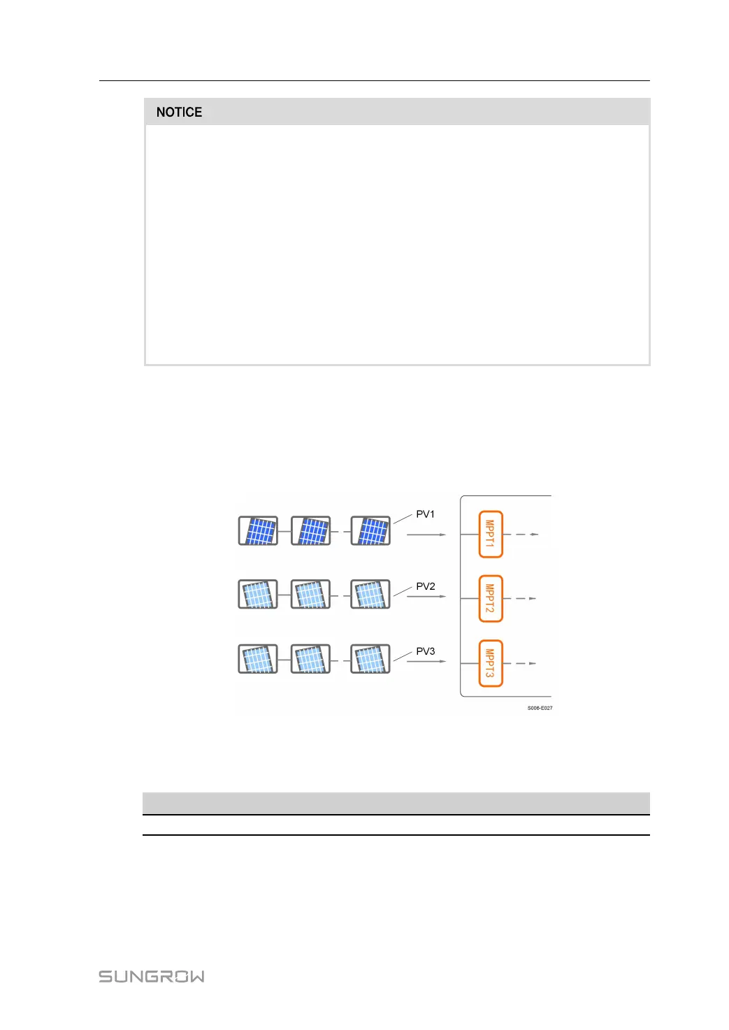
5.6.1 PV Input Configuration
• The inverters SG8.0RS-L/SG9.0RS-L/SG10RS-L have three PV inputs, each with inde-
pendent MPP tracker. Each DC input area can operate independently.
• The PV strings to each DC input may differ from each other, including PV module type,
number of PV modules in each string, angle of tilt, and installation orientation.
figure 5-2 PV Input Configuration
Prior to connecting the inverter to PV inputs, the specifications in the following table should
be met:
Inverter Model
Open-circuit Voltage Limit Max. current for input connector
All models
600 V 20 A
User Manual 5 Electrical Connection
 Loading...