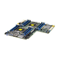
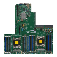
1-8
X10DRL-i Motherboard User’s Manual
• One (1) Back_panel COM Port (COM1)
• One (1) Serial Port Header (COM2)
Peripheral
Devices
USB Devices
• Two (2) USB 2.0 ports on the rear I/O panel (USB
0/1),
• Two (2) USB 3.0 ports on the rear I/O panel (USB
12/13)
• One (1) internal USB 2.0 header for two (2) USB front
panel support (USB 2/3)
• One (1) Type A USB 2.0 connector (USB 4)
• One (1) USB 3.0 header for two USB 3.0 connec-
tions (USB 8/9)
BIOS
• 16 MB SPI AMI BIOS
®
SM Flash UEFI BIOS
• APM 1.2, APCI 2.3, ACPI 1.0/2.0/3.0/4.0, USB Key-
board, Plug & Play (PnP) and SMBIOS 2.3
Power Con-
nectors
Power Connectors
• One (1) 24-pin ATX main power connector (J24)
• Two (2) 8-pin 12V power connectors (JPWR1/2)
Power
• ACPI/ACPM Power Management
Management
• Main switch override mechanism
• Power-on mode for AC power recovery
• Intel
®
Intelligent Power Node Manager 3.0 (Available
when the Supermicro Power Management (SPM) is
installed and special power supply used. See the
note on Page 1-14.)
• Management Engine (ME)
PC Health
PC Health/CPU Monitoring
Monitoring
• Onboard voltage monitoring for +3.3V, 3.3V Standby,
+5V, +5V Standby, +12V, CPU Core, Memory,
Chipset, and Battery Voltages
• CPU/System overheat LED and control
• CPU Thermal Trip support
• Status Monitor for Speed Control
• Status Monitor for On/Off Control
• CPU Thermal Design Power (TDP): support up to
145W (See Note 1 next page)

 Loading...
