2-32
X10DRL-i Motherboard User’s Manual
LE6
JBT1
BIOS
LICENSE
JPI2C1
J24
JPWR2
JF1
JD1
JL1
JSD1
BT1
JTPM1
JPL1
JPL2
JPG1
JPB1
JWD1
JI2C2
JPME2
JI2C1
JPF1
JPF2
J23
SP1
JUIDB1
LE2
LE1
LEDM1
FANB
FAN4
FAN3
FAN1
FAN5
FAN6
FANA
MAC CODE
BAR CODE
(3.0)
USB12/13
USB2/3
USB4
USB0/1
JSTBY1
JIPMB1
S-SATA2
S-SATA0
COM2
S-SATA1
S-SATA3
I-SATA5
PCH SLOT1 PCI-E 2.0
X4(IN X8)
I-SATA4
CPU1 SLOT2 PCI-E 3.0 X8
I-SATA3
I-SATA2
I-SATA1
CPU1 SLOT3 PCI-E 3.0 X8
I-SATA0
CPU2 SLOT4 PCI-E 3.0 X4 (IN X8)
CPU1 SLOT5 PCI-E 3.0 X16
CPU1 SLOT6 PCI-E 3.0 X8
UID
P2-DIMME1
P1-DIMMC1
P2-DIMMF1
P1-DIMMD1
P2-DIMMH1
P1-DIMMB1
VGA
P1-DIMMA1
CPU1
LAN2
P2-DIMMG1
CPU2
LAN1
IPMI_LAN
COM1
JPWR1
BMC
PCH
LAN CTRL
LAN CTRL
CLOSE 1st
OPEN 1st
CLOSE 1st
OPEN 1st
USB8/9(3.0)
BIOS
I-SGPIO1
S-SGPIO
1
J10
FAN2
X10DRL-i
Rev. 1.01
I-SGPIO2
IPMI CODE
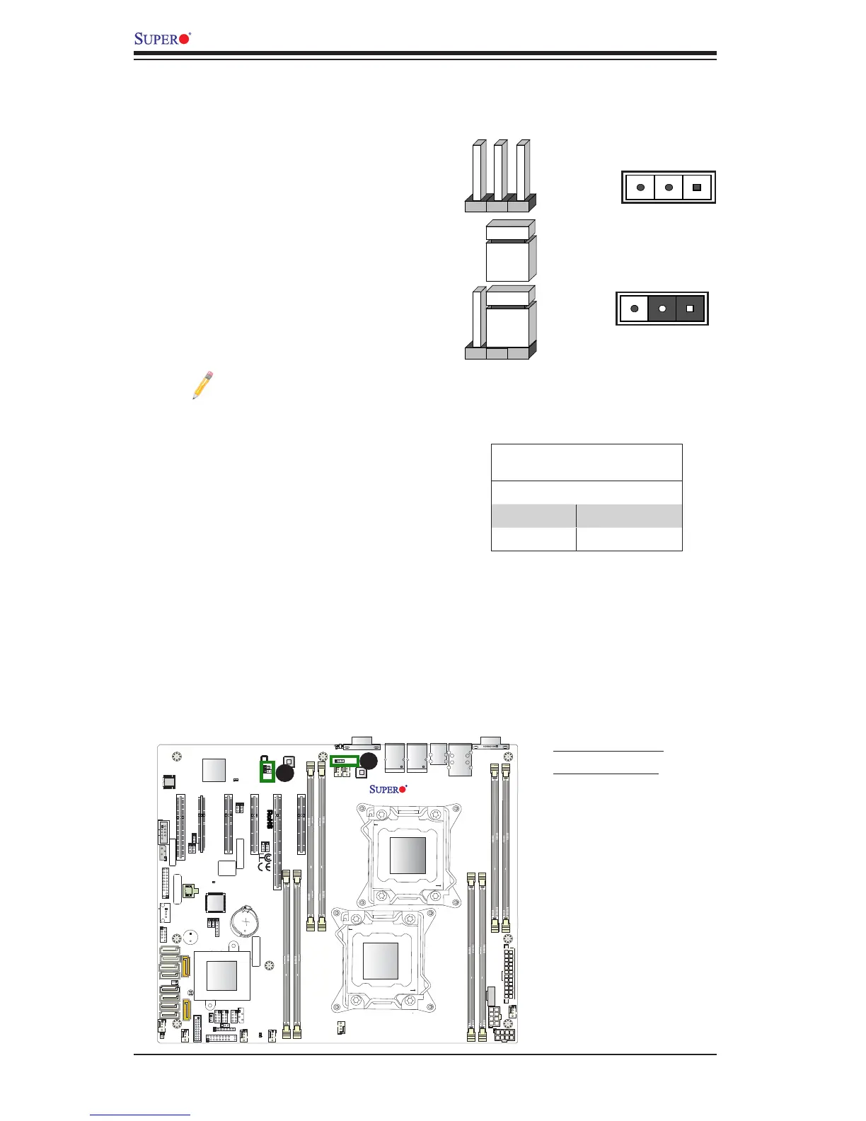
2-8 Jumper Settings
Explanation of Jumpers
To modify the operation of the mother-
board, jumpers can be used to choose
between optional settings. Jumpers create
shorts between two pins to change the
function of the connector. Pin 1 is identied
with a square solder pad on the printed
circuit board. See the motherboard layout
pages for jumper locations.
Note: On two pin jumpers,
"Closed" means the jumper is
on and "Open" means the jumper
is off the pins.
Pin 1-2 short
3 2 1
3 2 1
LAN Enable/Disable
Use JPL1 to enable or disable GLAN
Port 1, and use JPL2 to enable or disable
GLAN Port 2 on the motherboard. See the
table on the right for jumper settings. The
default setting is Enabled.
LAN Enable
Jumper Settings
Jumper Setting Denition
1-2 Enabled (default)
2-3 Disabled
A
A. GLAN1 Enable
B. GLAN2 Enable
B

 Loading...