EasyManuals Logo
Home>Supermicro>Motherboard>X10DRL-i SUPERO

Supermicro X10DRL-i SUPERO User Manual

Supermicro X10DRL-i SUPERO
121 pages
To Next Page IconTo Next Page
To Previous Page IconTo Previous Page
Page #39 background imageLoading...
Page #39 background image
Chapter 2: Installation
2-17
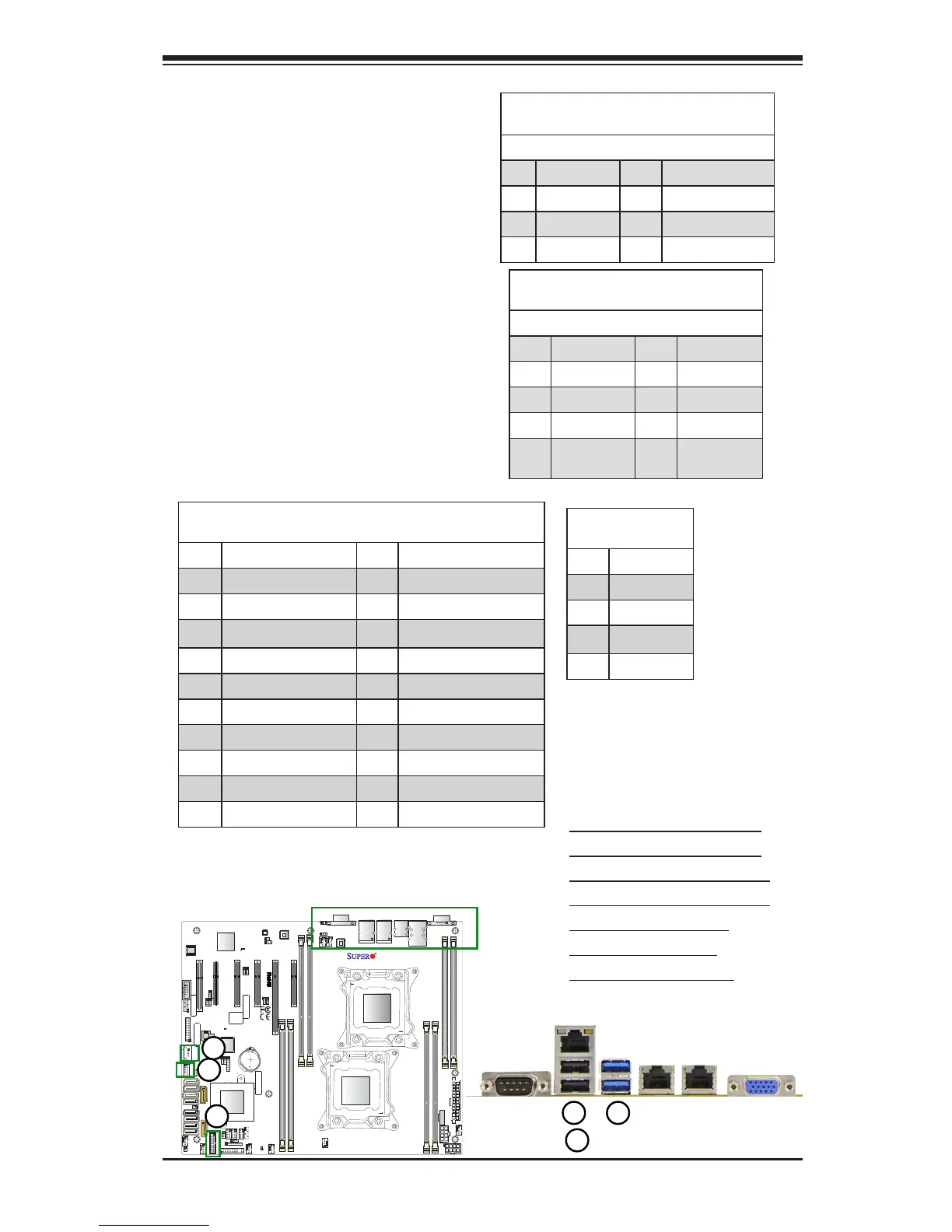
1. Backpanel USB0 (USB2.0)
2. Backpanel USB1 (USB2.0)
3. Backpanel USB12 (USB3.0)
4. Backpanel USB13 (USB3.0)
5. FP USB 2/3 (USB2.0)
6. FP USB 4 (USB2.0)
7. FP USB 8/9 (USB 3.0)
Universal Serial Bus (USB)
Two USB 2.0 ports (USB 0/1) and two
USB 3.0 ports (USB12/13) are located
on the I/O back panel on motherboard.
In addition, an internal USB header
(USB 2/3) and a Type A USB connec-
tor (USB 4) provide a total of three
USB 2.0 connections (USB 2/3, 4) for
front panel support. A USB 3.0 header,
located next to the Front Panel Control
(JF1), provides two front USB 3.0 con-
nections (USB 8/9). (Cables are not
included). See the tables on the right
and below for pin denitions.
LE6
JBT1
BIOS
LICENSE
JPI2C1
J24
JPWR2
JF1
JD1
JL1
JSD1
BT1
JTPM1
JPL1
JPL2
JPG1
JPB1
JWD1
JI2C2
JPME2
JI2C1
JPF1
JPF2
J23
SP1
JUIDB1
LE2
LE1
LEDM1
FANB
FAN4
FAN3
FAN1
FAN5
FAN6
FANA
MAC CODE
BAR CODE
(3.0)
USB12/13
USB2/3
USB4
USB0/1
JSTBY1
JIPMB1
S-SATA2
S-SATA0
COM2
S-SATA1
S-SATA3
I-SATA5
PCH SLOT1 PCI-E 2.0
X4(IN X8)
I-SATA4
CPU1 SLOT2 PCI-E 3.0 X8
I-SATA3
I-SATA2
I-SATA1
CPU1 SLOT3 PCI-E 3.0 X8
I-SATA0
CPU2 SLOT4 PCI-E 3.0 X4 (IN X8)
CPU1 SLOT5 PCI-E 3.0 X16
CPU1 SLOT6 PCI-E 3.0 X8
UID
P2-DIMME1
P1-DIMMC1
P2-DIMMF1
P1-DIMMD1
P2-DIMMH1
P1-DIMMB1
VGA
P1-DIMMA1
CPU1
LAN2
P2-DIMMG1
CPU2
LAN1
IPMI_LAN
COM1
JPWR1
BMC
PCH
LAN CTRL
LAN CTRL
CLOSE 1st
OPEN 1st
CLOSE 1st
OPEN 1st
USB8/9(3.0)
BIOS
I-SGPIO1
S-SGPIO
1
J10
FAN2
X10DRL-i
Rev. 1.01
I-SGPIO2
IPMI CODE
1
2
3
4
5
7
8
Back Panel USB (2.0) 0/1
Pin Denitions
Pin# Denition Pin# Denition
1 +5V 5 +5V
2 USB_PN0 6 USB_PN1
3 USB_PP0 7 USB_PP1
4 Ground 8 Ground
Front Panel USB (2.0) 2/3
Pin Denitions
Pin # Denition Pin # Denition
1 +5V 2 +5V
3 USB_PN2 4 USB_PN3
5 USB_PP2 6 USB_PP3
7 Ground 8 Ground
9 Key 10 No Connec-
tion
USB (3.0) USB 8/9, USB 12/13
Pin Denitions
Pin# Description Pin# Description
1 USB3.0_Front_VCC
2 USB3_RE_RXN6 19 USB3.0_Front_VCC
3 USB3_RE_RXP6 18 USB3_RE_RXN5
4 Ground 17 USB3_RE_RXP5
5 USB3_RE_TXN6 16 Ground
6 USB3_RE_TXP6 15 USB3_RE_TXN5
7 Ground 14 USB3_RE_TXP5
8 USB2_N8 13 Ground
9 USB2_P8 12 USB2_N9
10 Ground 11 USB2_P9
6
USB (2.0) USB 4
Pin Denitions
Pin# Description
1 +5V
2 USB_PN4
3 USB_PP4
4 Ground

Table of Contents

Questions and Answers:

Question and Answer IconNeed help?

Do you have a question about the Supermicro X10DRL-i SUPERO and is the answer not in the manual?

Supermicro X10DRL-i SUPERO Specifications

General IconGeneral
BrandSupermicro
ModelX10DRL-i SUPERO
CategoryMotherboard
LanguageEnglish

Related product manuals