EasyManuals Logo
Home>Supermicro>Motherboard>X10DRL-i SUPERO

Supermicro X10DRL-i SUPERO User Manual

Supermicro X10DRL-i SUPERO
121 pages
To Next Page IconTo Next Page
To Previous Page IconTo Previous Page
Page #47 background imageLoading...
Page #47 background image
Chapter 2: Installation
2-25
LE6
JBT1
BIOS
LICENSE
JPI2C1
J24
JPWR2
JF1
JD1
JL1
JSD1
BT1
JTPM1
JPL1
JPL2
JPG1
JPB1
JWD1
JI2C2
JPME2
JI2C1
JPF1
JPF2
J23
SP1
JUIDB1
LE2
LE1
LEDM1
FANB
FAN4
FAN3
FAN1
FAN5
FAN6
FANA
MAC CODE
BAR CODE
(3.0)
USB12/13
USB2/3
USB4
USB0/1
JSTBY1
JIPMB1
S-SATA2
S-SATA0
COM2
S-SATA1
S-SATA3
I-SATA5
PCH SLOT1 PCI-E 2.0
X4(IN X8)
I-SATA4
CPU1 SLOT2 PCI-E 3.0 X8
I-SATA3
I-SATA2
I-SATA1
CPU1 SLOT3 PCI-E 3.0 X8
I-SATA0
CPU2 SLOT4 PCI-E 3.0 X4 (IN X8)
CPU1 SLOT5 PCI-E 3.0 X16
CPU1 SLOT6 PCI-E 3.0 X8
UID
P2-DIMME1
P1-DIMMC1
P2-DIMMF1
P1-DIMMD1
P2-DIMMH1
P1-DIMMB1
VGA
P1-DIMMA1
CPU1
LAN2
P2-DIMMG1
CPU2
LAN1
IPMI_LAN
COM1
JPWR1
BMC
PCH
LAN CTRL
LAN CTRL
CLOSE 1st
OPEN 1st
CLOSE 1st
OPEN 1st
USB8/9(3.0)
BIOS
I-SGPIO1
S-SGPIO
1
J10
FAN2
X10DRL-i
Rev. 1.01
I-SGPIO2
IPMI CODE
Warning: To provide adequate power supply
to the motherboard, be sure to connect the
24-pin ATX PWR (J24), and the two 8-pin
PWR connectors (JPWR1, JPWR2) to the
power supply. Failure to do so may void the
manufacturer warranty on your power supply
and motherboard.
2-7 Connecting Cables
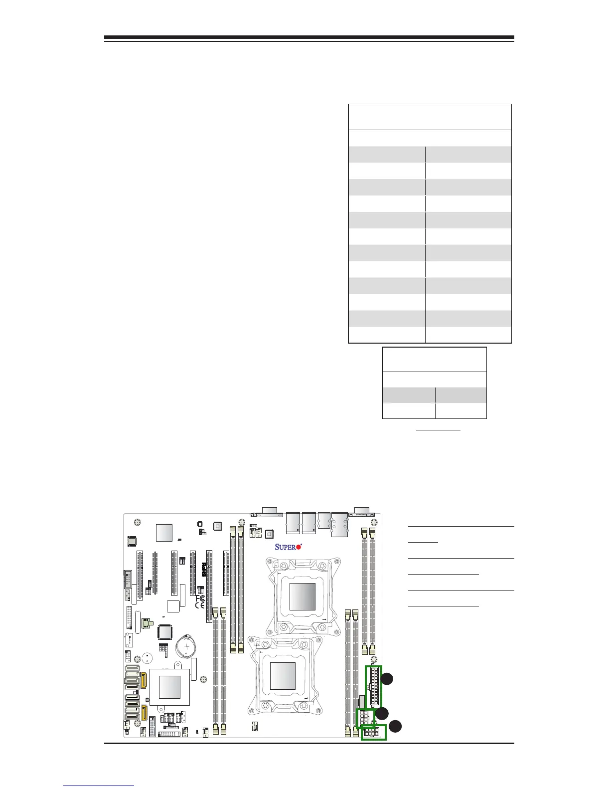
Power Connectors
A 24-pin main power supply connector
(J24), and two 8-pin CPU power connec-
tors (JPWR1/JPWR2) are located on the
motherboard. These power connectors
meet the SSI EPS 12V specication and
must be connected to your power supply
to provide adequate power to the system.
See the tables on the right for pin deni-
tions.
A. J24: 24-pin ATX PWR
(Req'd)
B. JPWR1: 8-pin Proces-
sor PWR (Req'd)
C. JPWR2: 8-pin Proces-
sor PWR (Req'd)
A
B
C
ATX Power 24-pin Connector
Pin Denitions (JPW1)
Pin# Denition Pin # Denition
13 +3.3V 1 +3.3V
14 -12V (NC) 2 +3.3V
15 GND 3 GND
16 PS_ON 4 +5V
17 GND 5 GND
18 GND 6 +5V
19 GND 7 GND
20 Res (NC) 8 PWR_OK
21 +5V 9 5VSB
22 +5V 10 +12V
23 +5V 11 +12V
24 GND 12 +3.3V
(Required)
12V 8-pin Power Connec-
tor Pin Denitions
Pins Denition
1 through 4 Ground
5 through 8 +12V

Table of Contents

Questions and Answers:

Question and Answer IconNeed help?

Do you have a question about the Supermicro X10DRL-i SUPERO and is the answer not in the manual?

Supermicro X10DRL-i SUPERO Specifications

General IconGeneral
BrandSupermicro
ModelX10DRL-i SUPERO
CategoryMotherboard
LanguageEnglish

Related product manuals