GS500K3 (’03-MODEL) 19-21
SIGNAL GENERATOR PEAK VOLTAGE
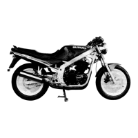
• Remove the seat.
• Disconnect the signal generator lead wire coupler.
NOTE:
Be sure that all couplers are connected properly and the battery
is in fully-charged condition.
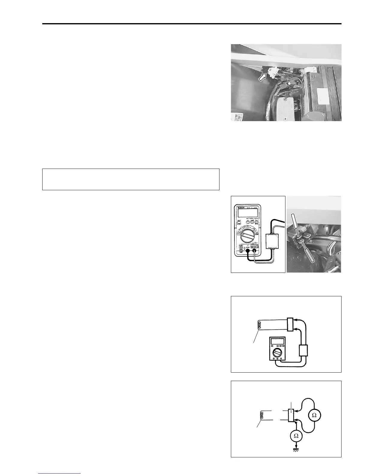
Inspect the signal generator peak voltage between Brown and
B/Bl lead wires on the signal generator lead wire coupler.
• Connect the tester with peak volt adaptor as follow.
Brown (
+ Probe) – B/Bl (
- Probe)
B/Bl: Black with Blue tracer
( 09900-25008: Multi circuit tester set
$
• Shift the transmission into the neutral.
• Turn the ignition switch to the “ON” position.
• Squeeze the clutch lever.
• Crank the engine a few seconds with starter motor by
depressing starter button and then check the signal generator
peak voltage.
• Repeat the above test procedure a few times and measure
the highest signal generator peak voltage.
) Tester knob indication: Voltage (*)
+ Signal generator peak voltage:
More than 1.8 V (Br – B/Bl)
If the peak voltage on the signal generator lead wire coupler is
abnormal, the signal generator must be replaced and recheck.
SIGNAL GENERATOR RESISTANCE
• Remove the frame cover and disconnect the signal generator
lead wire coupler.
• Measure the resistance between lead wires and ground. If the
resistance is not specified value, the signal coil must be
replaced.
+ Signal coil resistance: 250 – 420 Ω (Br – B/Bl)
∞ Ω (Br – Ground)
When using multi circuit tester and peak volt adaptor,
follow the instruction manual.
Signal
generator
coupler
Peak
volt
adaptor
Signal
generator
B/Bl
Br
Signal
generator
coupler
Signal
generator
 Loading...