19-22 GS500K3 (’03-MODEL)
REGULATOR/RECTIFIER
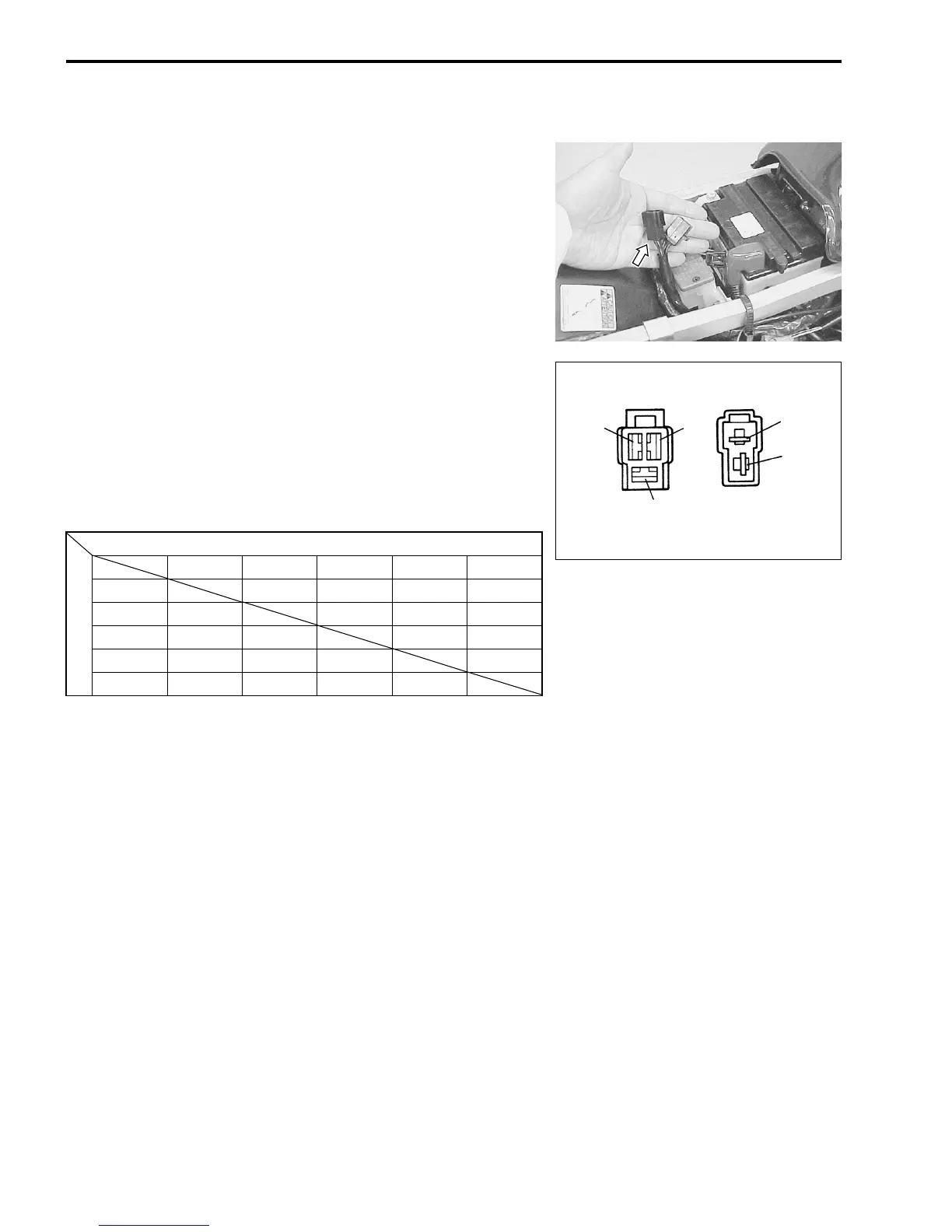
• Remove the seat.
• Diconnect the regulator/rectifier couplers.
Measure the voltage between the terminals using the multi cir-
cuit tester as indicated in the table below. If the voltage is not
within the specified value, replace the regulator/rectifier with a
new one.
( 09900-25008: Multi circuit tester set
- Tester knob indication: Diode test (.)
✽ More than 1.4 V (tester’s battery voltage)
NOTE:
If the tester reads under 1.4 V when the tester probes are not con-
nected, replace the battery of multi circuit tester.
Unit: V
+ Probe of tester to:
-
Probe of tester to:
Y
1
Y
2
Y
3
B/R B/W
Y
1
✽✽✽
0.4 – 0.7
Y
2
✽✽✽
0.4 – 0.7
Y
3
✽✽ ✽
0.4 – 0.7
B/R
0.4 – 0.7 0.4 – 0.7 0.4 – 0.7 0.5 – 1.2
B/W ✽✽✽✽
Y1
Y2
Y3
B/W
B/R

 Loading...