GS500K3 (’03-MODEL) 19-17
IGNITION SYSTEM
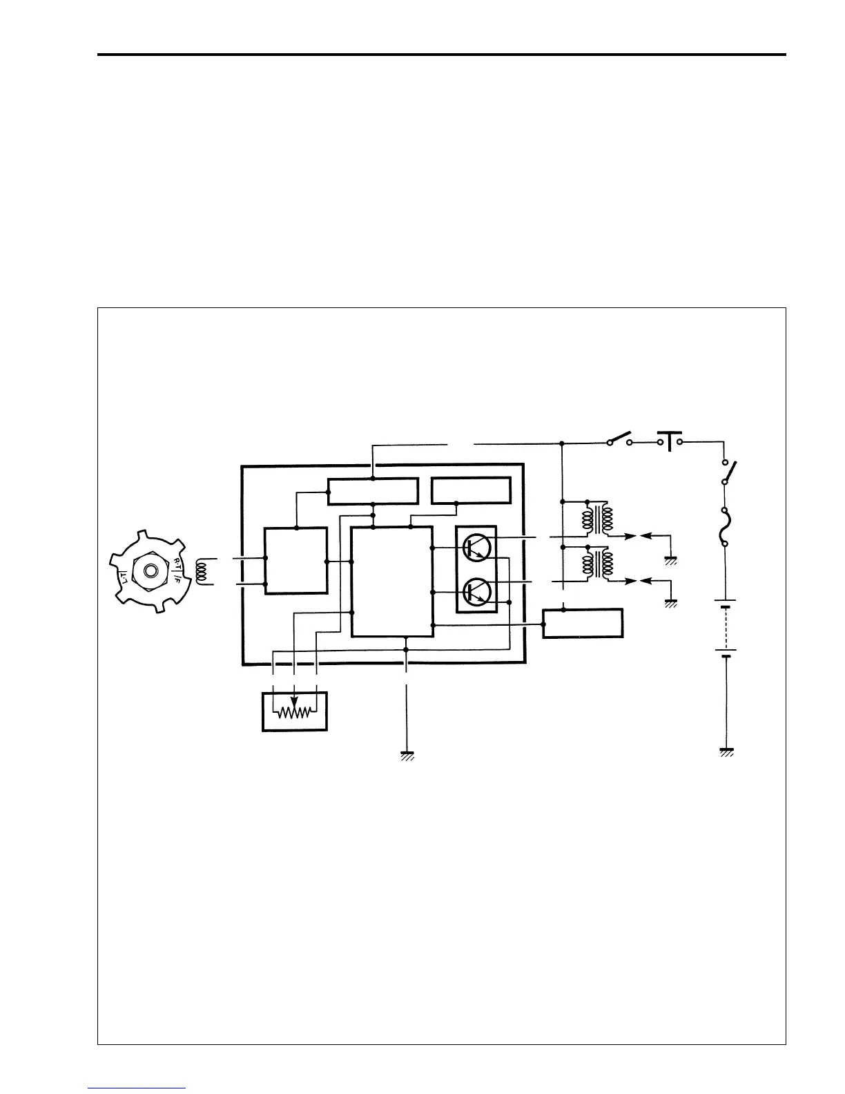
DESCRIPTION
The fully transistorized ignition system consists of a signal generator, ignitor unit, ignition coils and spark
plugs.
The signal generator mounted at the right end of the crankshaft comprises the rotor tip and pickup coil.
The induced signal in the signal generator is sent to wave-form arrangement circuit, and CPU receives this
signal and calculates the best ignition timing from the signal of ceramic vibrator. The CPU outputs signal to
the transistor of the I. G. coil output circuit which is connected to the primary windings of the ignition coil
which is turned OFF and ON accordingly, thus it induces the secondary current on the ignition coil second-
ary windings and produce the spark between spark plug gaps.
Signal generator
WIRE COLOR
B : Black
Bl : Blue
Br : Brown
R : Red
W : White
B/Bl : Black with Blue tracer
B/Y : Black with Yellow tracer
B/W : Black with White tracer
G/Bl : Green with Blue tracer
O/W : Orange with White tracer
R/B : Red with Black tracer
Br
B/Bl
Ignitor
O/W
Engine
stop
switch
Side-stand
relay
Ignition
switch
Fuse
(20 A)
Battery
(12 V)
B/W
Wave-
form
arrange-
ment
circuit
Ignition power
source circuit
CPU
Central
Processing
Unit
Ceramic vib
Ignition coil
W
B/Y
O/W
Solenoid
valve
()
BBlR
Throttole
position
sensor
(For GS500H)
 Loading...