17. Electrical System
17-17
Switch / Horn
Main switch
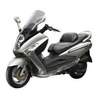
Inspection
Remove the front cover.
Disconnect the main switch coupler.
Check the continuity between two points as
indicted below
Replacement of main switch
Remove main switch cap.
Disconnect the coupler of the main switch and
loosen the mounting bolts (3 bolts).
Remove the main switch.
Install the new main switch and tighten the
mounting bolts.
Install the main switch coupler and cap.
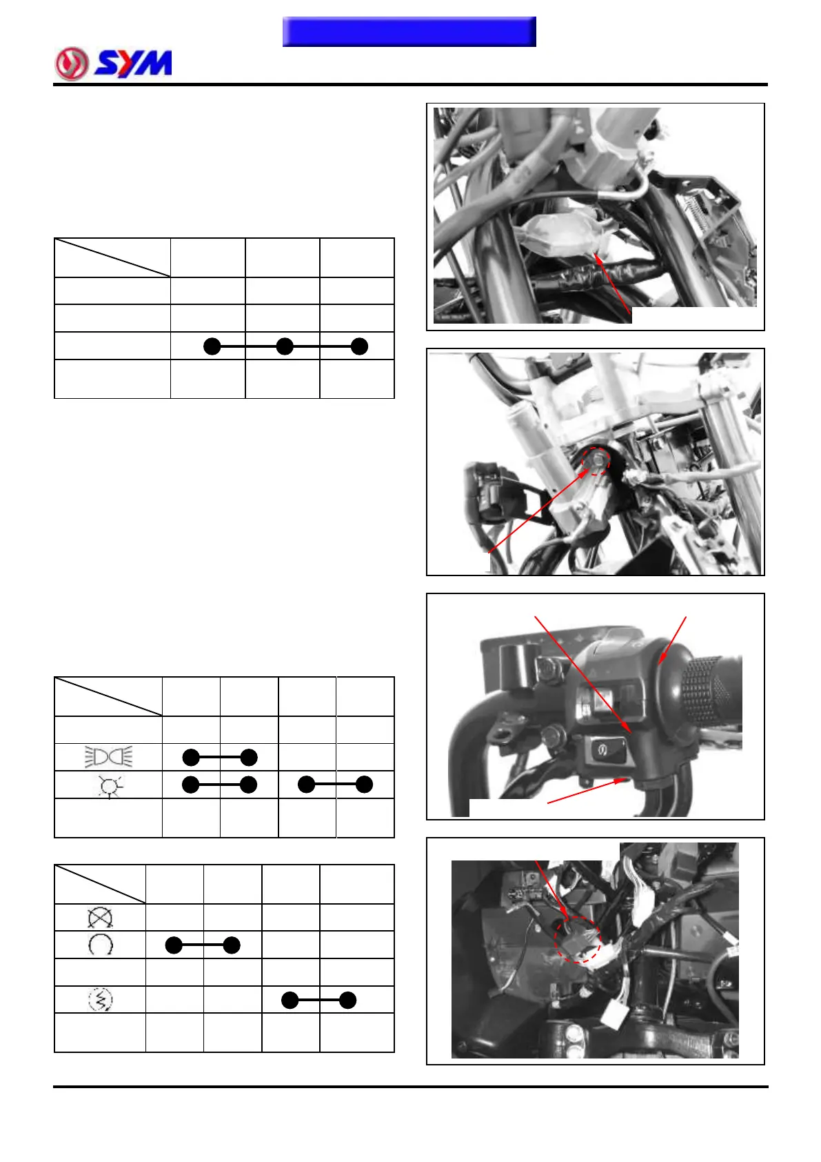
Right handle switch
Remove the handle cover and front cover.
Disconnect the coupler of right handle switch.
Check the continuity between two points as
indicated in the table below
Headlight switch
Engine start and stop switch
Right handle switch coupler
 Loading...