26 TA2922 Universal Line Interface Service Manual
© Tait Electronics Limited March 2010
4.3 SK1 I/O signal configuration
All nine of the lines on D-range connector SK1 are configured according to the
29 x 9 I/O matrix which can be factory SMD populated on the top side of the
board or configured by a technician placing solder links on specific pads in the
matrix on the bottom side of the board.
Important All variants of the TA2922 option board have all or some SK1 lines
configured using zero ohm resistors on the top side of the I/O
matrix. Before fitting solder links to the bottom side of the matrix,
it is essential to remove existing components from the top side of
the matrix, or check carefully that existing links do not conflict
with newly populated solder links on the bottom side. Failure to
do so may result in unexpected operation or permanent damage
to the TA2922 interface.
There are 26 individual signals which are assignable to any of the nine lines of SK1.
It is possible, and in some cases necessary, to link two signals to one SK1 pin. For
example, one side of the optocoupler can be connected to DC ground by fitting a
link between /PTT IN2 and a SK1 pin and a link from the same pin to GND.
Not all of the signals are available in the initial option board software release but
may be implemented in future software updates.
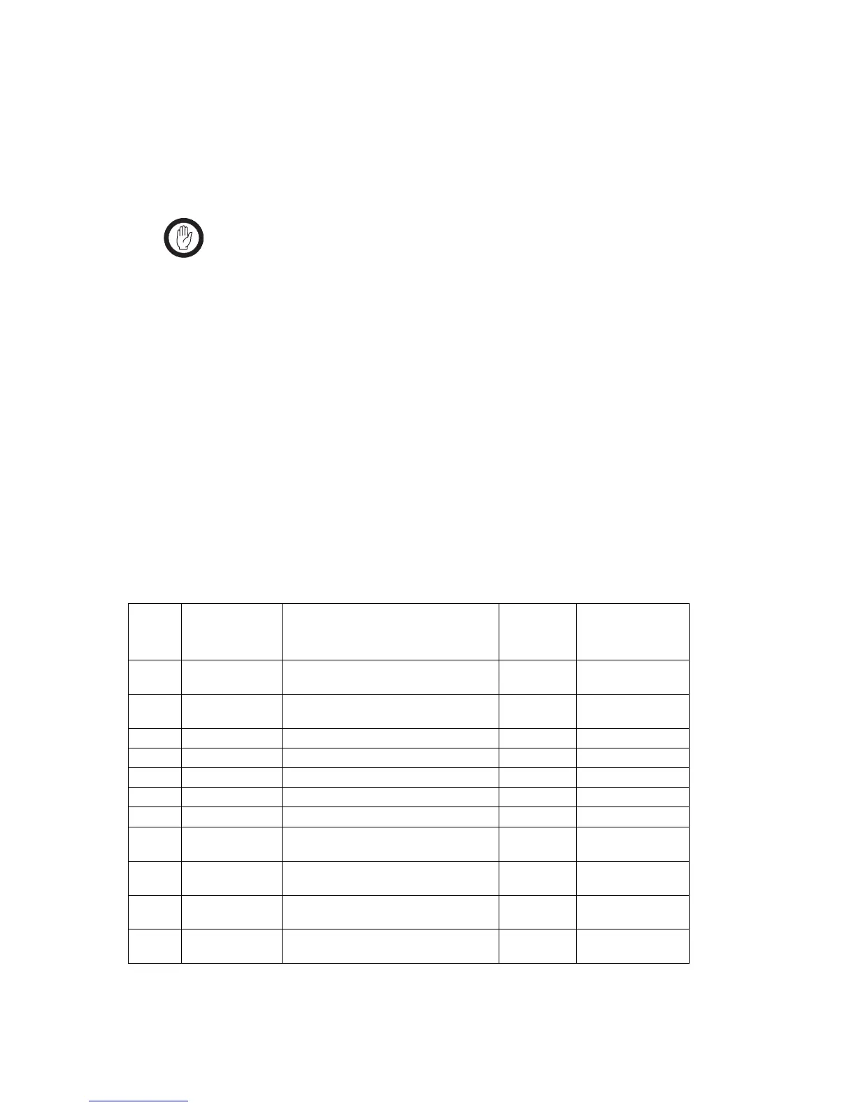
SK1 I/O signal summary
The 26 I/O signals configurable via the I/O matrix are:
Signal
Number
Signal Name Description
Direction
(relative to
TA2922)
Level
A LINE OUT 1 Balanced line output (4W) /balanced line
in/out (2W)
Output -30 to +10dBm into
600 ohms
B /GATE OUT 1 RX gate output via relay contacts,
configurable
Output 0-50VDC @1A
C GROUND Analogue/DC ground Bidirectional 0V
D /PTT IN 1 PTT input to opto-coupler Input 10-50VDC
E LINE IN 1 Balanced line input (4W) Input -30 to +5dBm
F LINE IN 2 Balanced line input (4W) Input -30 to +5dBm
G /PTT IN2 PTT input to opto-coupler Input 10-50VDC
H /GATE OUT 2 RX gate output via relay contacts,
configurable
Output 0-50VDC @1A
I LINE OUT 2 Balanced line output (4W) /balanced line
in/out (2W)
Output -30 to +10dBm into
600 ohms
J +13V8_SW Switched DC supply output, Output 10.8-16VDC
@150mA
K AUX MIC AUD Mic audio directly to the radio aux
microphone input
Input 2.3VDC 15mV RMS
 Loading...