38 TA2922 Universal Line Interface Service Manual
© Tait Electronics Limited March 2010
4.4 Additional configuration links
In addition to the 26 x 9 I/O matrix for configuring signals to the pins of SK1, a
range of other solder link pads exist for configuring:
■ 2-wire/4-wire operation
■ keying options
■ gate out relay operation
■ software profile configurations.
These bottom-side solder link pads can alternatively be fitted with top side 0603
resistor pads for the machine population of the hardware variants listed below. The
table below indicates the relationship between bottom side solder link pads and top
side resistor locations.
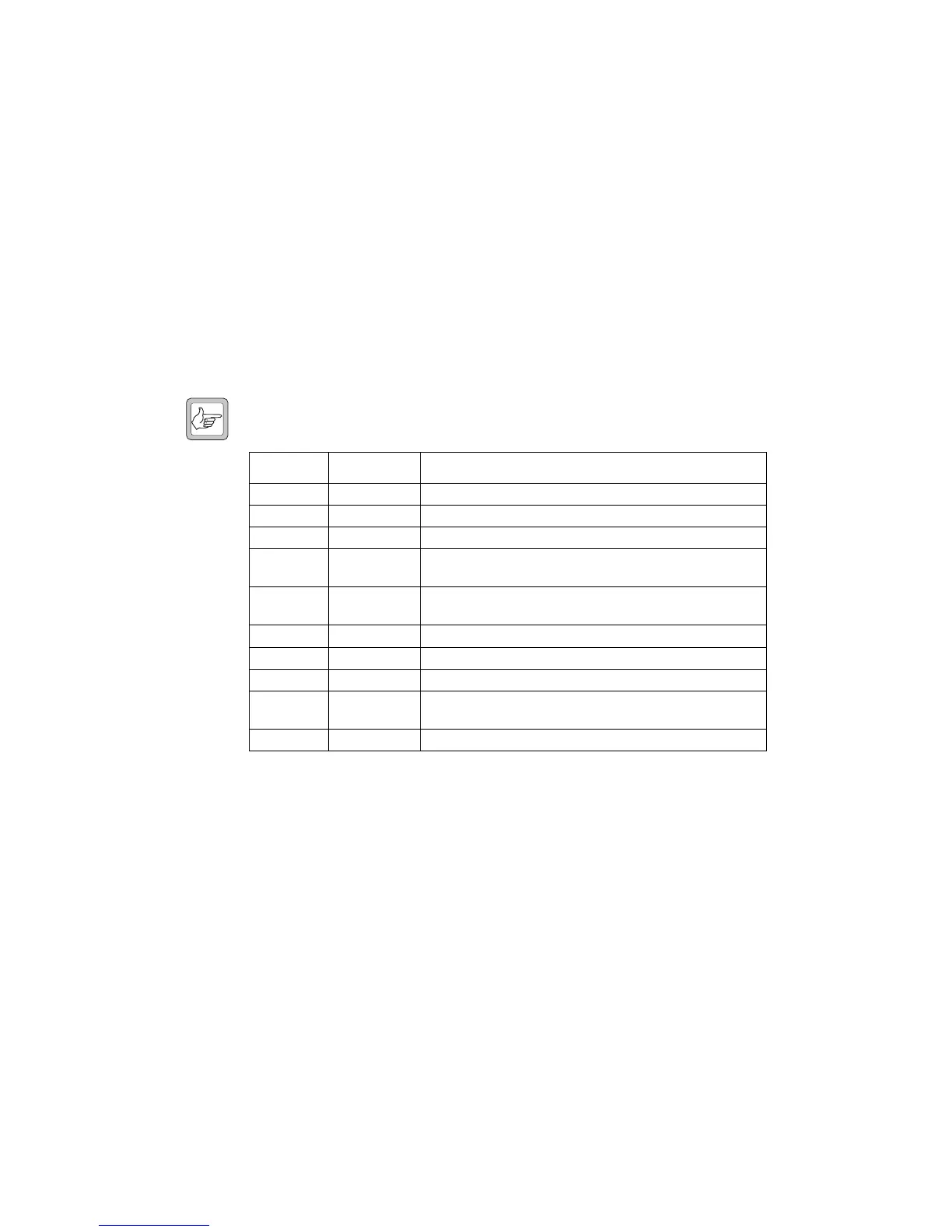
Note Some solder link pads are 2-way while others are 3-way links.
Solder link SMD resistor Description
LK1 1-2 R46 Connect normally open relay contact to /GATE OUT 1
LK1 2-3 R78 Connect normally closed relay contact to /GATE OUT 1
LK4 R62 Enable RX line audio from line TX pair (2-wire line operation)
LK5 1-2 R82 Connect 2-wire line transformer centre tap to RX gate relay
output
LK5 2-3 R80 Connect 2-wire line transformer centre tap to optocoupler
input
LK6 1-2 R77 Connect normally open relay contact to /PTT IN 1
LK6 2-3 R76 Connect normally closed relay contact to /PTT IN 1
LK7 R65 Connect +13.8V to relay common and /GATE OUT 2
LK8 R81 Connect half of optocoupler input and /PTT IN 2 to DC
ground
LK9 R42 Select configuration profile 2 (if enabled in programming)
 Loading...