5-36
5-4-3 Electronic Gear
Electronic gear ratio parameter can be used to scale the command output pulse.
This would be useful in transmission applications where move distance per move command pulse has
to be scaled due to mechanical requirements.
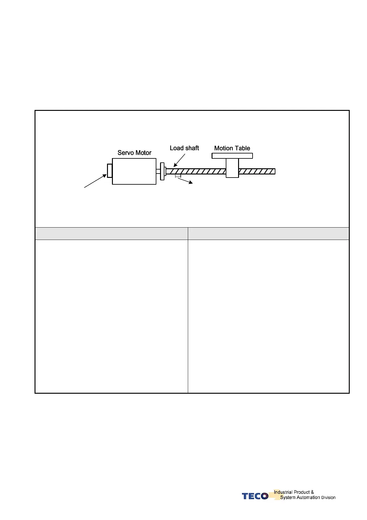
Diagram and notes below describe the electronic gear ratio effect.
Example of a transmission device and calculations that show the required number of pulses from a
host controller to move the table by 10mm.
Encoder pulse per
revolution(PPR)=2000
Screw Pitch = 5mm. (Move distance for
1revolution of screw)
Calculations without Electronic Gear Ratio Calculations with Electronic Gear Ratio
1. One rotation of ball screw = Table move distance of
5mm.
2. If the table is required to move 10mm, then Ball
screw needs to rotate by (10mm ÷ 5 mm/rev)= 2
Revs
3. Command pulses required to cause one revolution:-
= Encoder ppr × ( Internal multiplication factor).
= 2000 ppr x 4 = 8000 pulses.
4.So the Command pulses required to move 10mm (2
revs):-
= 8000 pulses x 2 (revs) = 16000 Pulses.
Number of command pulses for an specific move
distance can be calculated according to the formula
below:
= Number of Ball Screw Revs x (Encoder ppr x 4).
For Calculating the number of pulses command required,
Setting of Electronic gear ratio see next chapter.
Electronic gear ratio can be set according to the required
move distance per move command pulse.
For example:
1. One Pulse command = Move distance of 1μm.
2. If the Motion Table needs to move 10mm,
Then the required command pulses from a Host Controller
is
= 10mm ÷ 1μm / Pulse.= 10000 Pulses.
Once the move distance per pulse and the Electronic
gear ratio is known then the required number of pulse
command can be calculated.
 Loading...