4-5
4-2 Trial Operation for Servo motor without Load from
Host Reference
Check and ensure that all power connections to the drive and motor and control signal connection
between the host controller and the drive are correct.Motor must be mechanically disconnected from
the load.
Following section describes the trial run when using a host controller such as a PLC.
Two trial runs have been discussed. Speed control mode ( Section B) and Position control mode
( Section C).
Section A shows the connections and SON signal (servo on) requirements for both trial runs.
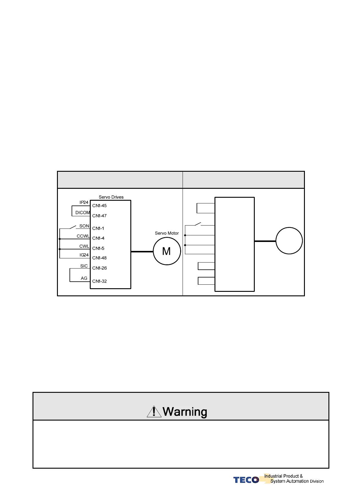
A. Launching Servo motor
Example wiring diagram:
Speed Control(Cn001=1) Position Control(Cn001=2)
M
CN1-14
CN1-15
CN1-16
CN1-17
Pulse
/Pulse
Sign
/Sign
SON
CCWL
CWL
CN1-1
CN1-4
CN1-5
CN1-45
CN1-47
CN1-48
IG24
IP24
DICOM
Servo Motor
Servo Drives
a. Disable Analog Input command terminals.
Speed control mode: Link analog input terminal SIN to 0V terminal (AG).
Position control mode: Link external pulse command terminals “Pulse” to ”/Pulse” and “Sign” to
“/Sign”.
b. Enable Servo ON Signal
Connect SON terminal to IG 24 (0V) terminal (Digital Ground).
On drive power up servo will be turned on. Now check for any Alarms. If any alarms then refer to
Chapter 8-2 for how to reset the Alarms.
To control the motor operating and stop, please input Torque/Speed/Position command after
Servo ON.
When input Torque/Speed/Position command, Please do not control the motor operating and stop
by using servo on signal.
 Loading...