GENERAL NOTES
A. Use sch em a tic d ia g ra m s , the o v e ro ll b lo c k
diag rom > c i r c u i t bo ard I ll u s t r a t io n s ) ond
c ir c u it d e s c r ip tio n s when o n o ly z ln g in stru m ent
m a lfu n c tio n s and lo c a tin g te s t p o in ts . The
sch em atic dia gram s in c lu d e ty p ic a l waveform s
ond v o lto g e s th a t o re in te n d e d os on o ld
in tro u b le s h o o tin g .
B. A lw ays set th e POWER s w itc h to OFF ond u nplu g
th e lin e c o rd b e fo re sw op pin g, re m o v in g , or
re p la c in g com ponents, ond b e fo re co n n e c tin g o r
d is c o nn e c tin g in s tru m e n t le a d s ond c a b le s .
C. When a na ly z in g c i r c u it m a lfu n c tio n s , c o n s id er
con n e c to rs and c o b le s os p o s s ib le causes o f
f o llu r e .
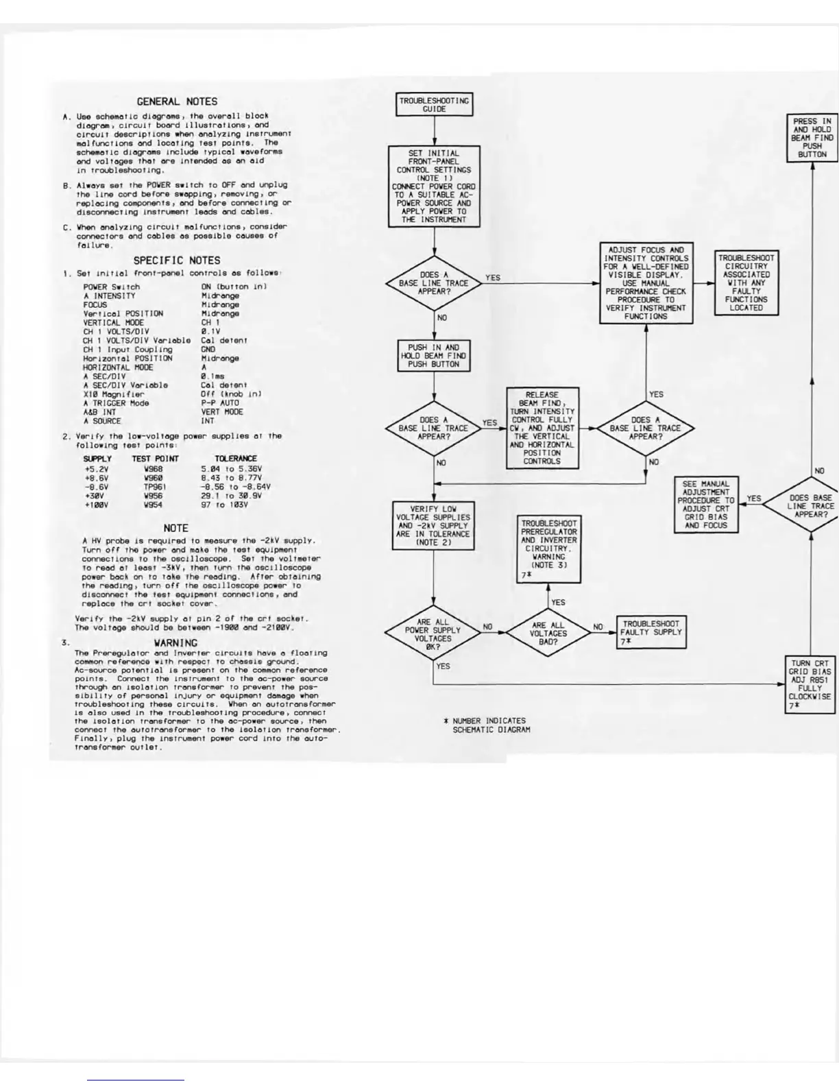
SPECIFIC NOTES
1. Set in i t i a l fro n t- p a n e l c o n tro ls as fo llo w s
POWER S w itc h
ON (b u tto n in )
A INTENSITY M idran ge
FOCUS
M ldro nge
V e r tic o l POSITION M idrange
VERTICAL MOOE
CH 1
CH 1 VOLTS/OIV 0.1V
CH 1 VOLTS/DIV V o r la b le C ol d e tent
CH 1 In put C o u p lin g GND
H o riz o n ta l POSITION
M idrang e
HORIZONTAL MODE
A
A SEC/OIV 0.1ms
A SEC/OIV V a ria b le
Col d e te n t
X I0 M o g n ifle r
O ff (knob in )
A TRIGGER Mode
P-P AUTO
A4B INT
VERT MODE
A SOURCE
I NT
V e rify th e lo w -vo lto g e power s u p p lie s o t the
fo llo w in g te s t p o in ts :
SUPPLY TEST POINT
TOLERANCE
♦5.2V W968
5.0 4 to 5.36V
+8.6V W960
8.4 3 to 8.77V
-8 .6 V TP961 -8 .5 6 to -8 .6 4 V
+30V W956
29.1 to 30.9V
♦100V W954
97 to 103V
NOTE
A HV p ro be 18 re q u ir e d to measure th e -2kV s u p p ly .
Turn o f f the power and make the te s t equipm ent
conn e c tio n s to the o s c illo s c o p e . Set the v o ltm e te r
to re ad o t le o st - 3 k V , then tu rn the o s c illo s c o p e
power back on to ta ke th e re a d in g. A fte r o b ta in in g
the r e a d in g , tu rn o f f th e o s c illo s c o p e power to
disco n n e c t the te s t equipm ent c o n n e ctio n s, ond
re pla ce the c r t so cke t cove r.
V e rify th e -2kV supp ly o t p in 2 o f th e c r t s o c ket.
The v o lto g e sho u ld be between -19 00 and -2100V.
3. WARNING
The P re re g u lo to r ond In v e r te r c ir c u its hove o f lo a t in g
common r e fe re n c e w ith re s p e c t to c h o s s is g rou nd .
A c-s o urc e p o te n tia l is pre s e n t on the common re fe re n c e
p o in ts . C onnect the in s tru m e n t to the oc-pow er sou rce
th ro ug h on is o lo t io n tra n sfo rm e r to p re vent the pos
s i b i l i t y o f p e rs o n a l in ju r y o r equipm ent damage when
tro u b le s h o o tin g these c ir c u its . When on o u to tra n sfo rm e r
is a ls o used in the tro u b le s h o o tin g pro ced u re , connect
th e is o la t io n tra n sfo rm e r to th e o c-p ow er s o urc e , then
connect th e o u to tra n s fo rm e r to the is o la tio n tra n sfo rm e r.
F in a lly , p lu g the in s tru m e n t pow er c o rd in to th e a u to -
tra n sfo rm e r o u t le t .
* NUMBER INDICATES
SCHEMATIC DIAGRAM