Performance Check Procedure—2215A Service
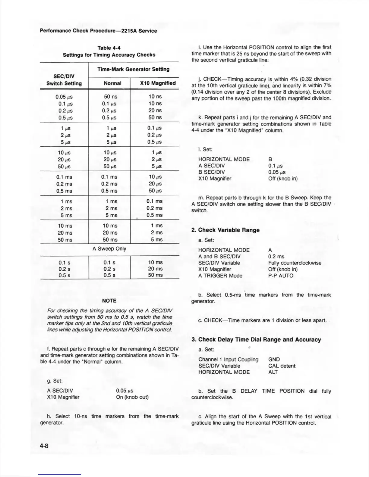
Table 4-4
Settings for Timing Accuracy Checks
SEC/DIV
Switch Setting
Time-Mark Generator Setting
Normal
X10 Magnified
0.05 ms
50 ns 10 ns
0.1 iis
0.1 iis
10 ns
0.2 ns
0.2 fis 20 ns
0.5 ms
0.5 ns 50 ns
1 /iS
1 fiS
0.1 MS
2 ns
2 ns
0.2 ms
5 ms
5 ns
0.5 ms
10 ms
10 MS
1 MS
20 ns 20 ms
2 MS
50 ms
50 ms
5 MS
0.1 ms
0.1 ms 10 MS
0.2 ms
0.2 ms
20 ms
0.5 ms
0.5 ms
50 ms
1 ms 1 ms
0.1 ms
2 ms
2 ms
0.2 ms
5 ms
5 ms
0.5 ms
10 ms
10 ms
1 ms
20 ms
20 ms
2 ms
50 ms
50 ms
5 ms
A Sweep Only
0.1 s
0.1 s
10 ms
0.2 s
0.2 s 20 ms
0.5 s
0.5 s
50 ms
i. Use the Horizontal POSITION control to align the first
time marker that is 25 ns beyond the start of the sweep with
the second vertical graticule line.
j. CHECK—Timing accuracy is within 4% (0.32 division
at the 10th vertical graticule line), and linearity is within 7%
(0.14 division over any 2 of the center 8 divisions). Exclude
any portion of the sweep past the 100th magnified division.
k. Repeat parts i and j for the remaining A SEC/DIV and
time-mark generator setting combinations shown in Table
4-4 under the "X I0 Magnified” column.
I. Set:
HORIZONTAL MODE B
A SEC/DIV 0.1
ns
B SEC/DIV 0.05
ns
X I0 Magnifier Off (knob in)
m. Repeat parts b through k for the B Sweep. Keep the
A SEC/DIV switch one setting slower than the B SEC/DIV
switch.
2. Check Variable Range
a. Set:
HORIZONTAL MODE
A and B SEC/DIV
SEC/DIV Variable
X I0 Magnifier
A TRIGGER Mode
A
0.2 ms
Fully counterclockwise
Off (knob in)
P-P AUTO
NOTE
For checking the timing accuracy o f the A SEC/DIV
switch settings from 50 m s to 0.5 s, watch the time
m arker tips only a t the 2nd and 10th vertical graticule
lines while adjusting the H orizontal POSITION control.
f. Repeat parts c through e for the remaining A SEC/DIV
and time-mark generator setting combinations shown in Ta
ble 4-4 under the "Normal” column.
g. Set:
A SEC/DIV 0.05
ns
X I0 Magnifier On (knob out)
h. Select 10-ns time markers from the time-mark
generator.
b. Select 0.5-ms time markers from the time-mark
generator.
c. CHECK—Time markers are 1 division or less apart.
3. Check Delay Time Dial Range and Accuracy
a. Set:
Channel 1 Input Coupling GND
SEC/DIV Variable CAL detent
HORIZONTAL MODE ALT
b. Set the B DELAY TIME POSITION dial fully
counterclockwise.
c. Align the start of the A Sweep with the 1st vertical
graticule line using the Horizontal POSITION control.
4-8

 Loading...


