Performance Check Procedure—2215A Service
TRIGGER
Equipment Required (see Table 4-1):
Leveled Sine-Wave Generator (Item 2) 50-fi BNC Termination (Item 5)
50-fi BNC Cable (Item 4)
INITIAL CONTROL SETTINGS b. Set the generator to produce a 5-MHz, 3-division
display.
Vertical
POSITION (both)
Midrange
VERTICAL MODE
CH 1
BW LIMIT
Off (button out)
CH 1 VOLTS/DIV
5 mV
CH 2 VOLTS/DIV 50 mV
VOLTS/DIV Variable
(both)
CAL detent
INVERT
Off (button out)
Input Coupling (both)
DC
srizontal
POSITION
Midrange
HORIZONTAL MODE A
A and B SEC/DIV
0.2
ns
SEC/DIV Variable
CAL detent
X I0 Magnifier Off (knob in)
B DELAY TIME POSITION
Fully counterclockwise
TRIGGER
SLOPE OUT
LEVEL Midrange
TRIGGER
VAR HOLDOFF
NORM
Mode
P-P AUTO
SLOPE
OUT
LEVEL Midrange
A&B INT CH 1
A SOURCE INT
A EXT COUPLING
DC
PROCEDURE STEPS
1. Check Internal Triggering
a. Connect the leveled sine-wave generator output via a
50-fi cable and a 50-fi termination to the CH 1 OR X input
connector.
c. Set the CH 1 VOLTS/DIV switch to 50 mV.
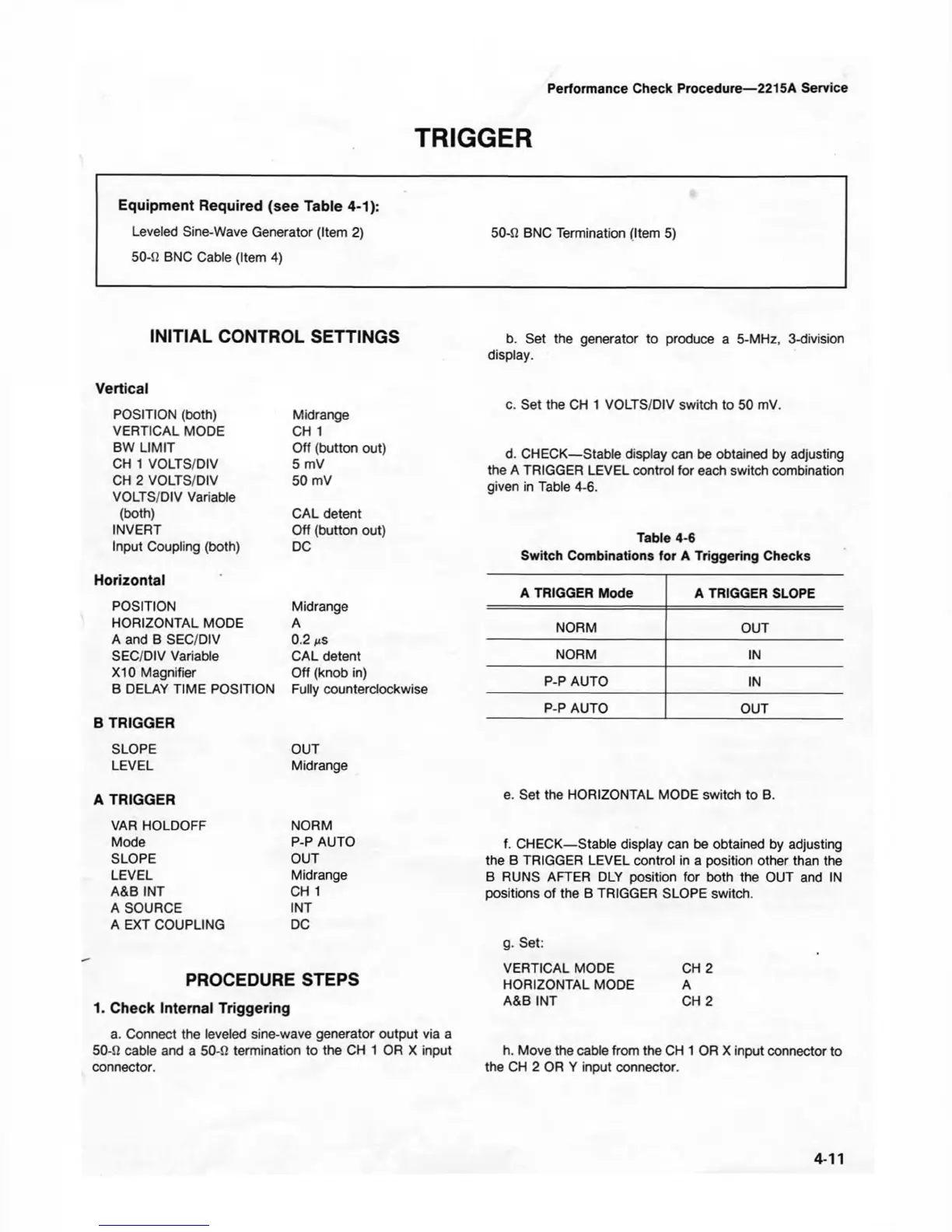
d. CHECK— Stable display can be obtained by adjusting
the A TRIGGER LEVEL control for each switch combination
given in Table 4-6.
Table 4-6
Switch Combinations for A Triggering Checks
A TRIGGER Mode
A TRIGGER SLOPE
NORM OUT
NORM
IN
P-P AUTO IN
P-P AUTO OUT
e. Set the HORIZONTAL MODE switch to B.
f. CHECK—Stable display can be obtained by adjusting
the B TRIGGER LEVEL control in a position other than the
B RUNS AFTER DLY position for both the OUT and IN
positions of the B TRIGGER SLOPE switch.
g. Set:
VERTICAL MODE CH 2
HORIZONTAL MODE A
A&B INT CH 2
h. Move the cable from the CH 1 OR X input connector to
the CH 2 OR Y input connector.
4-11