Theory of Operation—2215A Service
FROM A SWEEP
GENERATOR
FROM B SWEEP
GENERATOR
FROM ALTERNATE
DISPLAY
SWITCHING LOGIC
FROM A TRIGGER
FROM A SEC /DIV
SWITCH
TO CRT
HORIZ
DEFLECTION
PLATES
C4206-1I
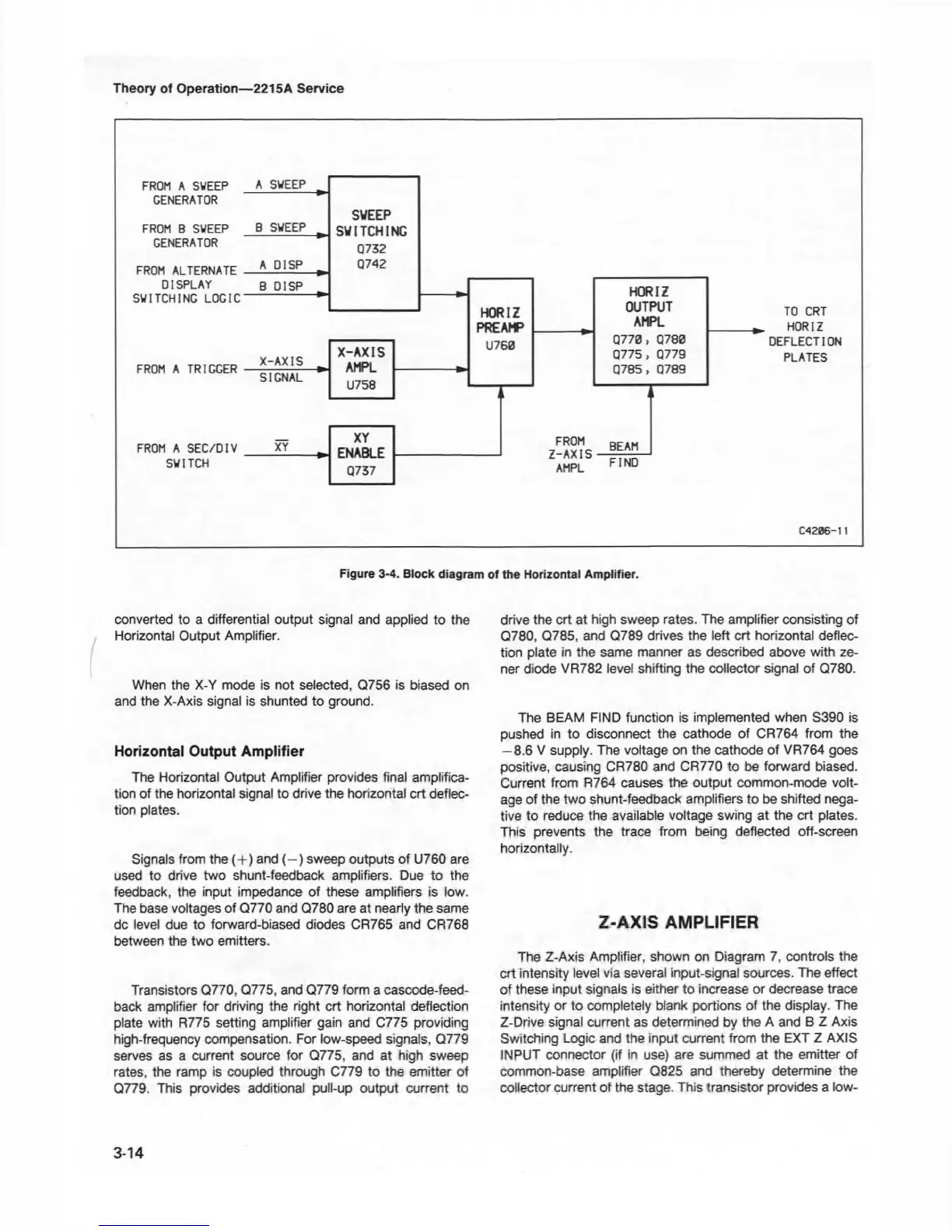
Figure 3-4. Block diagram of the Horizontal Amplifier.
converted to a differential output signal and applied to the
Horizontal Output Amplifier.
When the X-Y mode is not selected, Q756 is biased on
and the X-Axis signal is shunted to ground.
Horizontal Output Amplifier
The Horizontal Output Amplifier provides final amplifica
tion of the horizontal signal to drive the horizontal crt deflec
tion plates.
Signals from the (+) and ( - ) sweep outputs of U760 are
used to drive two shunt-feedback amplifiers. Due to the
feedback, the input impedance of these amplifiers is low.
The base voltages of Q770 and Q780 are at nearly the same
dc level due to forward-biased diodes CR765 and CR768
between the two emitters.
Transistors Q770, Q775, and Q779 form a cascode-feed-
back amplifier for driving the right crt horizontal deflection
plate with R775 setting amplifier gain and C775 providing
high-frequency compensation. For low-speed signals, Q779
serves as a current source for Q775, and at high sweep
rates, the ramp is coupled through C779 to the emitter of
Q779. This provides additional pull-up output current to
drive the crt at high sweep rates. The amplifier consisting of
Q780, Q785, and Q789 drives the left crt horizontal deflec
tion plate in the same manner as described above with ze-
ner diode VR782 level shifting the collector signal of Q780.
The BEAM FIND function is implemented when S390 is
pushed in to disconnect the cathode of CR764 from the
-8 .6 V supply. The voltage on the cathode of VR764 goes
positive, causing CR780 and CR770 to be forward biased.
Current from R764 causes the output common-mode volt
age of the two shunt-feedback amplifiers to be shifted nega
tive to reduce the available voltage swing at the crt plates.
This prevents the trace from being deflected off-screen
horizontally.
Z-AXIS AMPLIFIER
The Z-Axis Amplifier, shown on Diagram 7, controls the
crt intensity level via several input-signal sources. The effect
of these input signals is either to increase or decrease trace
intensity or to completely blank portions of the display. The
Z-Drive signal current as determined by the A and B Z Axis
Switching Logic and the input current from the EXT Z AXIS
INPUT connector (if in use) are summed at the emitter of
common-base amplifier Q825 and thereby determine the
collector current of the stage. This transistor provides a low-
3-14

 Loading...


