Operating Instructions—2215A Service
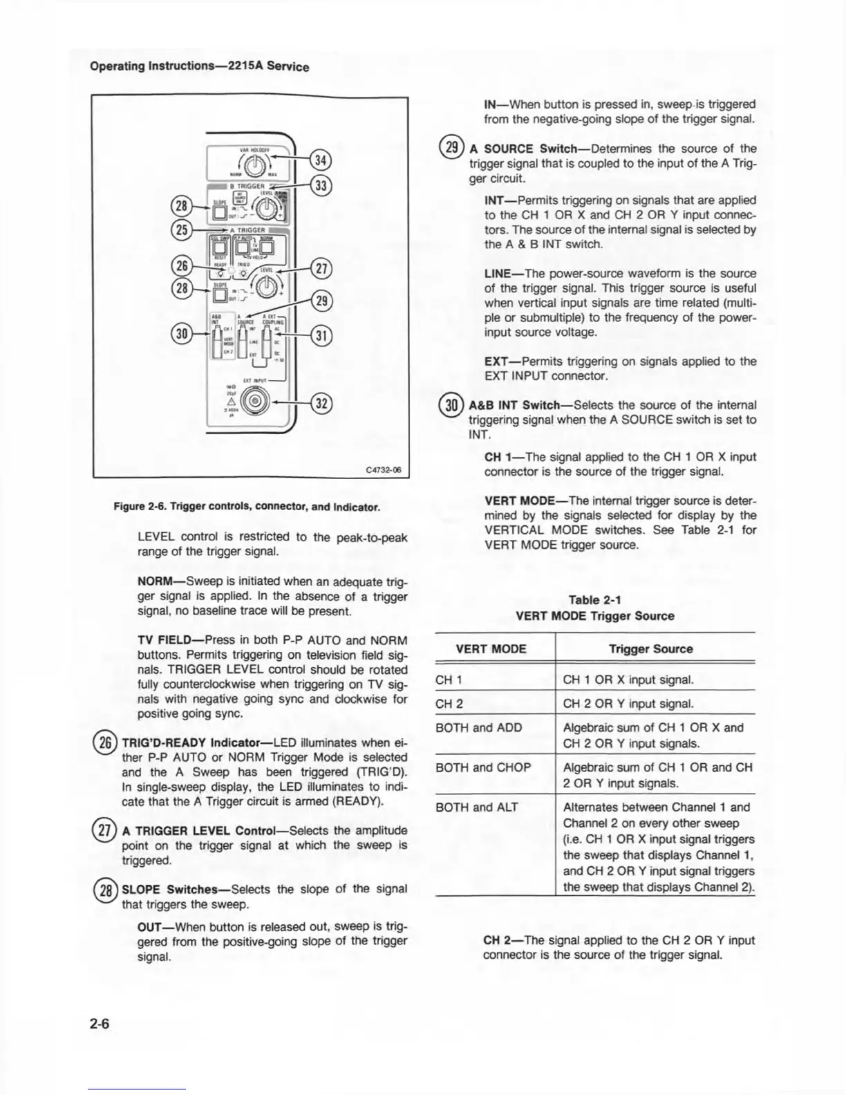
Figure 2-6. Trigger controls, connector, and Indicator.
LEVEL control is restricted to the peak-to-peak
range of the trigger signal.
NORM— Sweep is initiated when an adequate trig
ger signal is applied. In the absence of a trigger
signal, no baseline trace will be present.
TV FIELD—Press in both P-P AUTO and NORM
buttons. Permits triggering on television field sig
nals. TRIGGER LEVEL control should be rotated
fully counterclockwise when triggering on TV sig
nals with negative going sync and clockwise for
positive going sync.
(26) TRIG’D-READY Indicator—LED illuminates when ei
ther P-P AUTO or NORM Trigger Mode is selected
and the A Sweep has been triggered (TRIG’D).
In single-sweep display, the LED illuminates to indi
cate that the A Trigger circuit is armed (READY).
(27) A TRIGGER LEVEL Control—Selects the amplitude
point on the trigger signal at which the sweep is
triggered.
n jj) SLOPE Switches—Selects the slope of the signal
that triggers the sweep.
OUT—When button is released out, sweep is trig
gered from the positive-going slope of the trigger
signal.
IN—When button is pressed in, sweep is triggered
from the negative-going slope of the trigger signal.
(29) A SOURCE Switch— Determines the source of the
trigger signal that is coupled to the input of the A Trig
ger circuit.
INT— Permits triggering on signals that are applied
to the CH 1 OR X and CH 2 OR Y input connec
tors. The source of the internal signal is selected by
the A & B INT switch.
LINE—The power-source waveform is the source
of the trigger signal. This trigger source is useful
when vertical input signals are time related (multi
ple or submultiple) to the frequency of the power-
input source voltage.
EXT— Permits triggering on signals applied to the
EXT INPUT connector.
(30) A&B INT Switch—Selects the source of the internal
triggering signal when the A SOURCE switch is set to
INT.
CH 1—The signal applied to the CH 1 OR X input
connector is the source of the trigger signal.
VERT MODE—The internal trigger source is deter
mined by the signals selected for display by the
VERTICAL MODE switches. See Table 2-1 for
VERT MODE trigger source.
Table 2-1
VERT MODE Trigger Source
VERT MODE
Trigger Source
CH 1
CH 1 OR X input signal.
CH 2 CH 2 OR Y input signal.
BOTH and ADD Algebraic sum of CH 1 OR X and
CH 2 OR Y input signals.
BOTH and CHOP Algebraic sum of CH 1 OR and CH
2 OR Y input signals.
BOTH and ALT Alternates between Channel 1 and
Channel 2 on every other sweep
(i.e. CH 1 OR X input signal triggers
the sweep that displays Channel 1,
and CH 2 OR Y input signal triggers
the sweep that displays Channel 2).
CH 2—The signal applied to the CH 2 OR Y input
connector is the source of the trigger signal.
2-6

 Loading...


