Adjustment Procedure—2215A Service
POWER SUPPLY AND CRT DISPLAY
Equipment Required (See Table 4-1):
Leveled Sine-Wave Generator (Item 2) Digital Voltmeter (Item 10)
Time-Mark Generator (Item 3) DC Voltmeter (Item 12)
50-0 BNC Cable (Item 4)
Screwdriver (Item 13)
50-0 BNC Termination (Item 5)
See
ADJUSTMENT LOCATIONSS I
a t the back o f this m anual fo r location o f test points and adjustm ents.
INITIAL CONTROL SETTINGS
Vertical
POSITION (both)
Midrange
VERTICAL MODE
CH 1
CH 1 VOLTS/DIV
10 mV
CH 1 VOLTS/DIV Variable
CAL detent
Channel 1 Input Coupling
GND
srizontal
POSITION
Midrange
HORIZONTAL MODE
A
A SEC/DIV
X-Y
SEC/DIV Variable
CAL detent
X I0 Magnifier
Off (knob in)
TRIGGER
VAR HOLDOFF
NORM
Mode
P-P AUTO
SLOPE
OUT
LEVEL
Midrange
A&B INT
VERT MODE
A SOURCE
INT
PROCEDURE STEPS
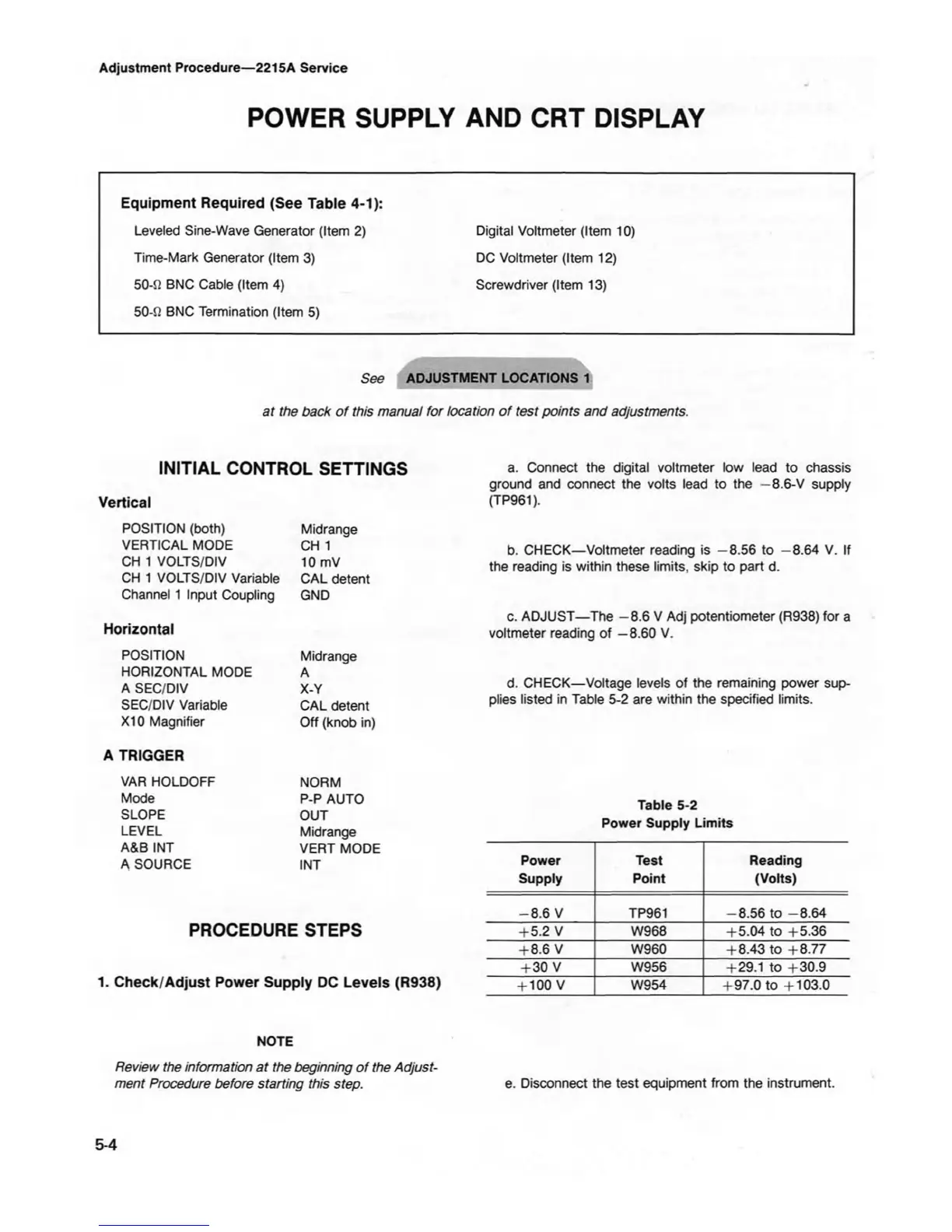
1. Check/Adjust Power Supply DC Levels (R938)
a. Connect the digital voltmeter low lead to chassis
ground and connect the volts lead to the -8.6-V supply
(TP961).
b. CHECK—Voltmeter reading is —8.56 to -8.64 V. If
the reading is within these limits, skip to part d.
c. ADJUST—The —8.6 V Adj potentiometer (R938) for a
voltmeter reading of -8.60 V.
d. CHECK—Voltage levels of the remaining power sup
plies listed in Table 5-2 are within the specified limits.
Table 5-2
Power Supply Limits
Power
Test
Reading
Supply Point (Volts)
-8 .6 V
TP961
-8.56 to -8.64
+ 5.2 V W968 + 5.04 to +5.36
+ 8.6 V
W960 + 8.43 to +8.77
+ 30 V
W956 +29.1 to +30.9
+ 100 V
W954
+ 97.0 to +103.0
NOTE
Review the information a t the beginning o f the Adjust
m ent Procedure before starting this step.
5-4
e. Disconnect the test equipment from the instrument.

 Loading...


