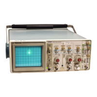
Performance Check Procedure—2215A Service
o. CHECK—Display amplitude is 0.6 division or less. c. Set the generator to produce a 25-MHz, 5-division
display.
p. Disconnect the test equipment from the instrument.
d. Set the VERTICAL MODE switch to CH 2.
e. CHECK— Display amplitude is 0.05 division or less.
5. Check Channel Isolation
a. Set:
VERTICAL MODE
VOLTS/DIV (both)
VOLTS/DIV Variable (both)
INVERT
Channel 2 Input Coupling
A SEC/DIV
CH 1
1 V
CAL detent
Off (button out)
GND
0.1 ns
f. Move the cable from the CH 1 OR X input connector to
the CH 2 OR Y input connector.
g. Set:
VERTICAL MODE CH 1
Channel 1 Input Coupling GND
Channel 2 Input Coupling DC
h. CHECK— Display amplitude is 0.05 division or less.
b. Connect the leveled sine-wave generator output via a
50-0 cable and a 50-0 termination to the CH 1 OR X input
connector. j. Disconnect the test equipment from the instrument.
4-6

 Loading...