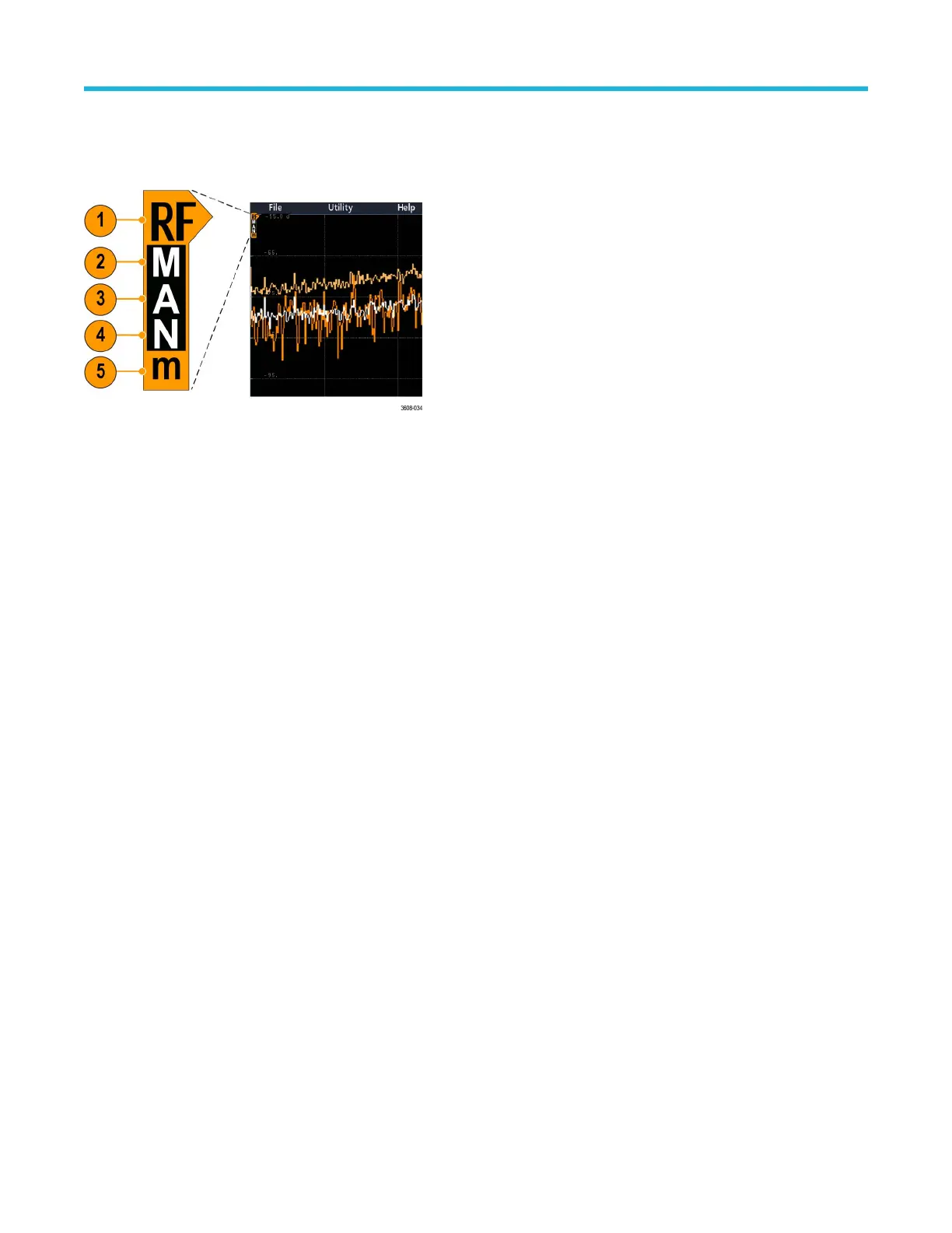
Spectrum trace handle
The spectrum trace handle provides details on the trace reference level, the source channel for the trace, and which trace types are
displayed.
Figure 5: Spectrum trace MANm handle info
1. The RF trace indicator is placed at the Reference Level. The waveform view shows the spectrum traces relative to a Reference Level
reference point. If the Reference level is above the top of the graticule, the handle is drawn at the top of the graticule and pointing up.
2. A capital M indicates that the maximum trace is enabled.
3. A capital A indicates that the average trace is enabled.
4. A capital N indicates that the normal trace is enabled.
5. The small m indicates that the minimum trace is enabled.
Highlighting around a letter indicates that trace type is selected. In the figure, the small m is highlighted, indicating that the minimum trace
is currently selected.
There is an important distinction between enabled and selected traces:
•
An enabled trace letter (displayed in the trace handle) means that trace type is being displayed.
• A selected trace (highlighted around the letter) is the trace that is used for measurements, marker readouts, and cursor readouts.
Waveform acquisition concepts
3 Series Mixed Domain Oscilloscope Printable Help 240

 Loading...