Section 8—485/R485 Service
DIAGRAMS AND CIRCUIT BOARD ILLUSTRATIONS
Symbols and Reference Designators
Electrical components shown on the diagrams are in the following units unless noted otherwise:
Capacitors = Values one or greater are in picofarads (pF).
Values less than one are in microfarads (pF).
Resistors = Ohms (£2)
Symbols used on the diagrams are based on USA Standard Y32.2-1967.
Logic symbology is based on MIL-STD-806B in terms of positive logic. Logic symbols depict the logic function performed
and may differ from the manufacturer's data.
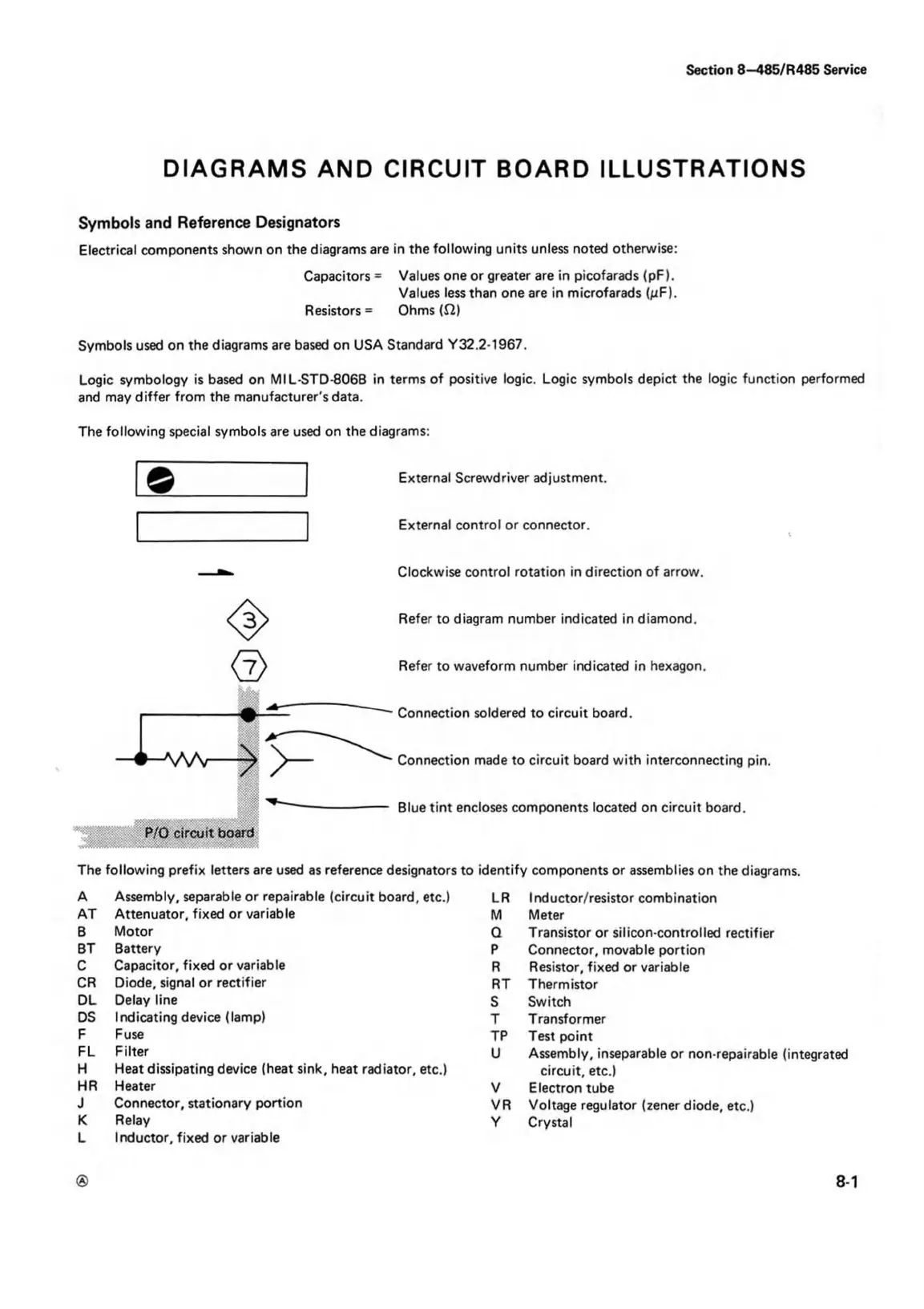
The following special symbols are used on the diagrams:
External Screwdriver adjustment.
External control or connector.
Clockwise control rotation in direction of arrow.
Refer to diagram number indicated in diamond.
Refer to waveform number indicated in hexagon.
Connection soldered to circuit board.
Connection made to circuit board with interconnecting pin.
Blue tint encloses components located on circuit board.
The following prefix letters are used as reference designators to identify components or assemblies on the diagrams.
A Assembly, separable or repairable (circuit board, etc.)
AT Attenuator, fixed or variable
B Motor
BT Battery
C Capacitor, fixed or variable
CR Diode, signal or rectifier
DL Delay line
DS Indicating device (lamp)
F Fuse
FL Filter
H Heat dissipating device (heat sink, heat radiator, etc.)
HR Heater
J Connector, stationary portion
K Relay
L Inductor, fixed or variable
LR Inductor/resistor combination
M Meter
Q Transistor or silicon-controlled rectifier
P Connector, movable portion
R Resistor, fixed or variable
RT Thermistor
S Switch
T Transformer
TP Test point
U Assembly, inseparable or non-repairable (integrated
circuit, etc.)
V Electron tube
VR Voltage regulator (zener diode, etc.)
Y Crystal
® 8-1

 Loading...


